
Electronically controlled high-load material press machine

A high-load, electronically controlled technology, which is applied to presses, presses using rotating pressure components, manufacturing tools, etc., can solve the problems affecting the guiding accuracy and the inconvenient operation of axial pressure detection, monitoring, installation and disassembly, and achieve In order to achieve the effect of convenient disassembly and removal of the test piece, compact structure and easy assembly without the expected effect and other problems

Inactive Publication Date: 2016-08-24
CHONGQING MASITER PRECISION MACHINERY
View PDF6 Cites 0 Cited by
  • Summary
  • Abstract
  • Description
  • Claims
  • Application Information

AI Technical Summary

Problems solved by technology

If the gap between the sliding bushing and the guide column is too large, it will affect the detection and monitoring of the guiding accuracy and axial pressure, and the expected effect will not be achieved; if the guiding accuracy is improved by reducing the fit clearance, the machining accuracy and assembly The accuracy has put forward very strict requirements, which will greatly increase the production cost
[0003] The loading device on the rotary press is generally composed of powertrain, upper slide plate, lower slide plate, positioning block, loading rod and pressure head, etc. The connection structure between the components is complicated, not only inconvenient to install and disassemble, but also low in assembly efficiency. Moreover, the loading rod is prone to offset, and the reliability of the transmission is poor
The indenter is usually a short cylindrical structure, which has a large contact area with the forming cylinder during the pressing process, which not only increases energy consumption, but also is prone to wear and damage

Method used


Image

  • Electronically controlled high-load material press machine

Examples


Embodiment Construction

[0018] Below in conjunction with accompanying drawing and embodiment the present invention will be further described:

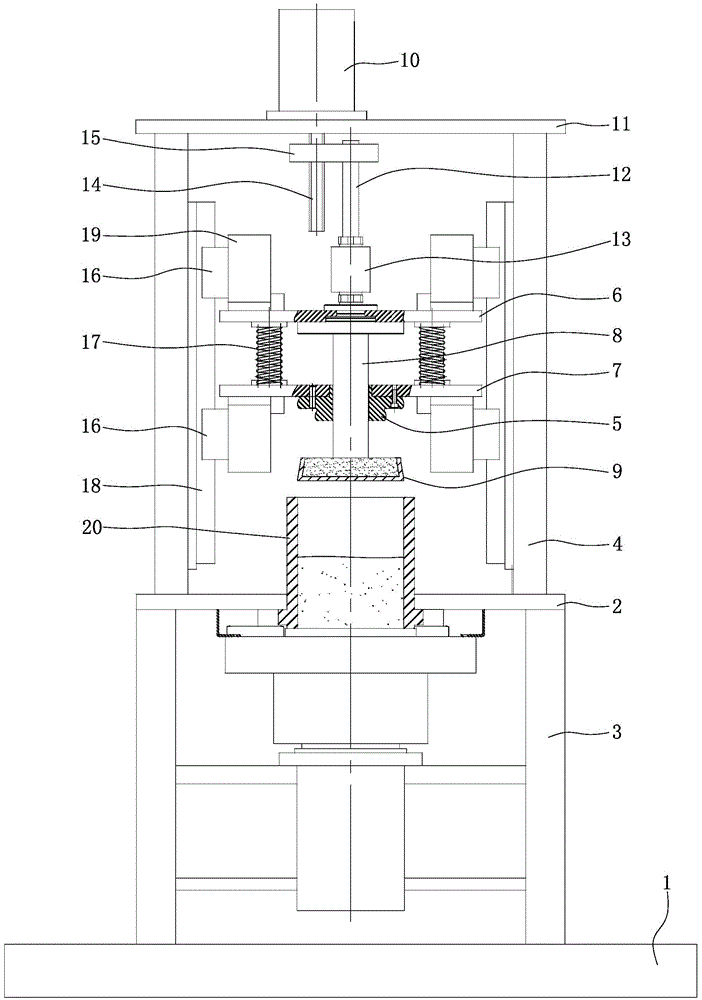
[0019] like figure 1 As shown, the base 1 is a rectangular plate structure, and is fixed to the bottom surface by anchor bolts. A support plate 2 is arranged directly above the base 1 , the support plate 2 is rectangular and parallel to the base 1 , and the support plate 2 is connected to the base 1 through four columns 3 distributed in a rectangle. The column 3 is perpendicular to the supporting plate 2, and the column 3 is preferably a hollow cylinder. The top of the column 3 is welded to the corner of the bottom of the supporting plate 2, and the bottom of the column 3 is welded to the base 1. Two left-right symmetrical guide columns 4 are arranged above the supporting plate 2 , the guiding columns 4 are rectangular tubes, and the guiding columns 4 are perpendicular to the supporting plate 2 . The tops of the two guide columns 4 jointly support the top p...


PUM


Abstract

The invention discloses an electronically controlled high-load material pressing machine. A pressing head 9 adopts a frustum structure with a small top and a big bottom; a forming cylinder (20) penetrates through the middle of a support plate (2); the forming cylinder (20) adopts a straight steel sleeve structure; an upper slide plate (6) and a lower slide plate (7) are connected with each other through springs (17); positioning seats (19) are fixed at the left end and the right end of the top of the upper slide plate (6) and the left end and the right end of the bottom of the lower slide plate (7); and slide blocks (17) are mounted on the side surfaces, facing guide pillars (4) on corresponding sides, of the positioning seats (19). The electronically controlled high-load material pressing machine is reasonable in design, easy to implement, low in cost, simple in connection structure, convenient to mount, dismount and operate and high in assembly efficiency, not only can prevent a loading rod from deviation, but also can ensure the reliability of transmission; the contact area between the pressing head and the forming cylinder is small, so that the pressing head is not liable to be damaged by abrasion and achieves a longer service life; and meanwhile, the slide blocks are in zero clearance fit with linear guide rails, so that the guide accuracy can be improved effectively, and the loading capacity is enhanced.

Description

technical field [0001] The invention relates to a pressing machine, in particular to an electronically controlled high-load material pressing machine. Background technique [0002] The rotary press is a special equipment used to press the required construction or engineering materials into standard test pieces. Existing rotary presses generally adopt a guiding mechanism in which sliding bearings and guiding columns are matched, through the cooperation of two guiding columns on the frame and sliding bushings, so as to achieve guidance and withstand the lateral force and bending moment generated during the pressing process. If the gap between the sliding bushing and the guide column is too large, it will affect the detection and monitoring of the guiding accuracy and axial pressure, and the expected effect will not be achieved; if the guiding accuracy is improved by reducing the fit clearance, the machining accuracy and assembly The accuracy has put forward very strict requir...

Claims


Application Information

Patent Timeline
Patent Type & Authority Patents(China)
IPC IPC(8): B30B3/00B30B15/04B30B15/06
Inventor 杨勇
Owner CHONGQING MASITER PRECISION MACHINERY
Learn More