Drainage structure of dehumidifier

A technology of drainage structure and dehumidifier, which is used in household heating, lighting and heating equipment, space heating and ventilation, etc., can solve problems such as water tank damage and safety accidents, and achieve increased capacity, improved drainage performance, and improved use of handy effect

Inactive Publication Date: 2005-12-28
LG ELECTRONICS (TIANJIN) APPLIANCES CO LTD
View PDF0 Cites 13 Cited by
  • Summary
  • Abstract
  • Description
  • Claims
  • Application Information

AI Technical Summary

Problems solved by technology

[0015] Therefore, it is not only impossible to make the through hole of the drain pipe connection port (14) in the family without special tools, but also the water tank (12) will be damaged and a safety accident will occur due to the carelessness of the user when connecting. are also possible

Method used


Image

  • Drainage structure of dehumidifier
  • Drainage structure of dehumidifier
  • Drainage structure of dehumidifier

Examples


Embodiment Construction

[0048] In order to further understand the content, characteristics and effects of the present invention, the following examples are given, and detailed descriptions are as follows in conjunction with the accompanying drawings

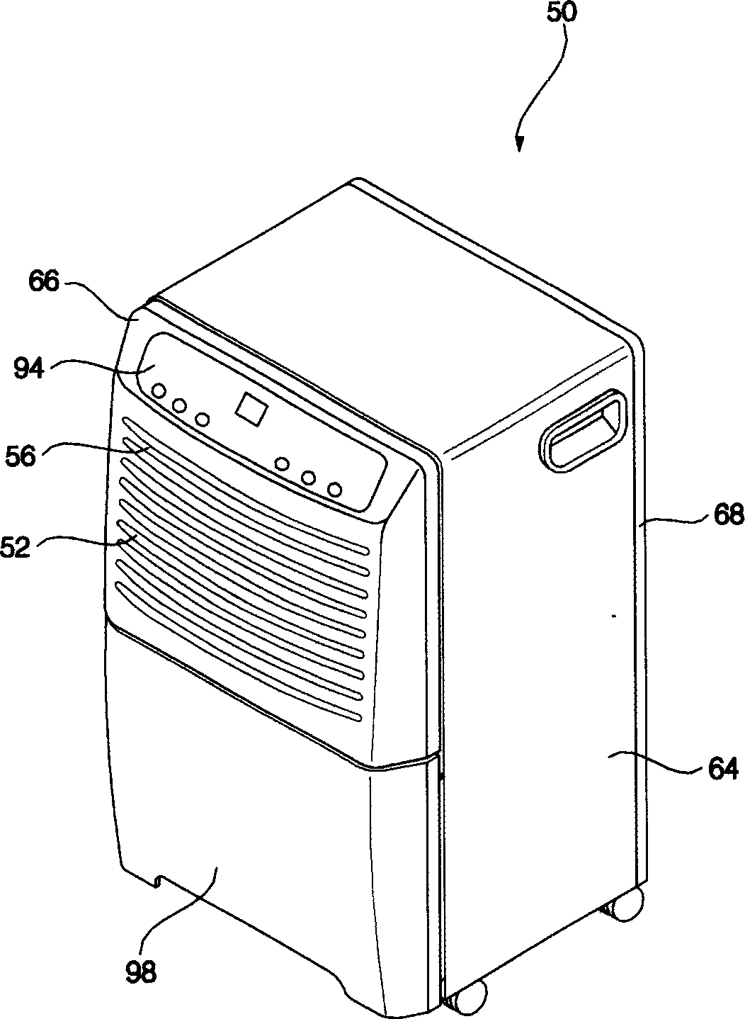
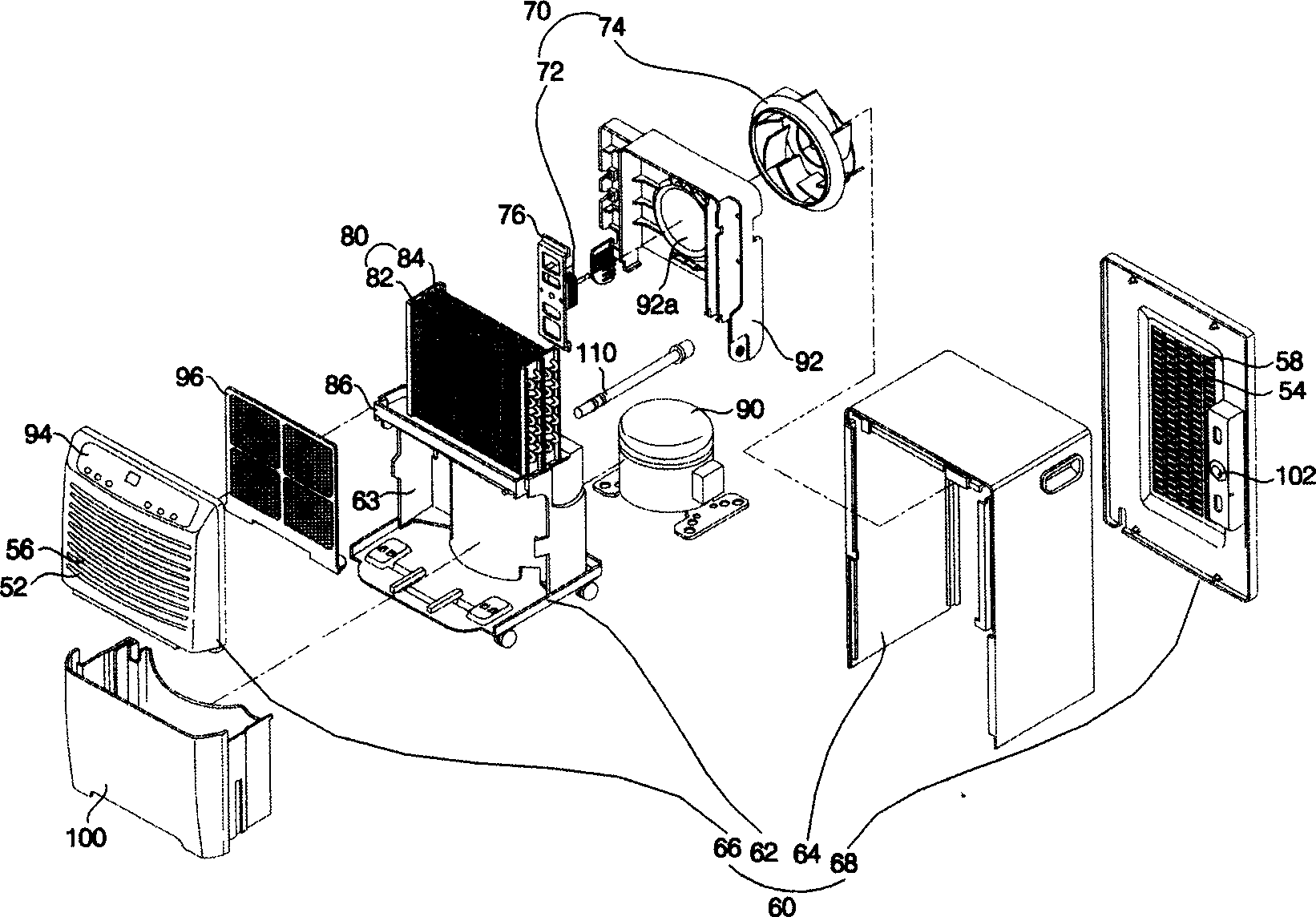
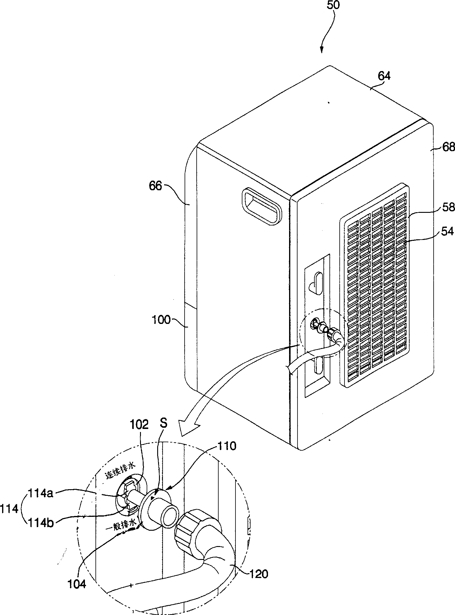
[0049] figure 1 is the view of the dehumidifier in the present invention, figure 2 It is an exploded view of the dehumidifier in the present invention, image 3 It is an exploded view of the drainage structure of the dehumidifier in the present invention, Figure 4 It is a structural diagram of the general drainage structure of the dehumidifier in the present invention, Figure 5 It is a structural diagram of the continuous drainage structure of the dehumidifier in the present invention, Figure 6 It is the view of the connecting pipe of the dehumidifier in the present invention.

[0050] The dehumidifier in the present invention is as figure 1 with figure 2 As shown, mainly form the air inlet (52) by the front, and the chassis (60) that forms...


PUM


Abstract

A draining structure of demoistener for draining in ordinary mode or continuous mode has a casing containing a heat exchanger, a draining tray with draining outlet for collecting the condensed water dropped from heat exchanger, a water tank under said draining outlet, a draining tube for draining the condensed water from said draining outlet, and a connecting tube able to be turned for making a selection between water tank and draining tube, that is, selecting ordinary mode or continuous mode.

Description

technical field [0001] The invention belongs to the technology of dehumidifiers, and in particular relates to a drainage structure of a dehumidifier which can easily change the drainage operation of condensed water from general drainage to continuous drainage. Background technique [0002] Generally speaking, the dehumidifier introduces the humid air in the room into the inside of the chassis, reduces the humidity through a heat exchanger composed of an evaporator and a condenser with refrigerant flow, and then discharges the dehumidified air into the room to reduce the humidity of the room. device for humidity purposes. [0003] Figure 7 It is an exploded view of a dehumidifier produced by conventional technology, Figure 8 It is a cross-sectional view of a general drainage structure of a dehumidifier produced by conventional techniques. Figure 9 It is a view of the continuous drainage structure of the dehumidifier produced by the conventional technology. [0004] Dehu...

Claims


Application Information

Patent Timeline
Patent Type & Authority Applications(China)
IPC IPC(8): F24F3/14
Inventor 李先烈
Owner LG ELECTRONICS (TIANJIN) APPLIANCES CO LTD
Why Eureka
Try Eureka