Failsafe differential amplifier circuit

A fail-safe and auxiliary amplifier technology, applied in the direction of differential amplifiers, amplifier combinations, DC-coupled DC amplifiers, etc., can solve the problems of input differential signal equipment not connected to the system, input differential signal attenuation, etc.

Inactive Publication Date: 2005-12-28
FAIRCHILD SEMICON CORP
View PDF0 Cites 2 Cited by
  • Summary
  • Abstract
  • Description
  • Claims
  • Application Information

AI Technical Summary

Problems solved by technology

[0007] 1. The input differential signal decays below the specified threshold
[0008] 2. The input differential signal is reduced to 0 volts (cable short circuit, line short circuit, wiring short circuit, etc.)
[0009] 3. Input differential signal goes into undriven, unknown state or floating input (open cable, device not connected to system, etc.)

Method used


Image

  • Failsafe differential amplifier circuit
  • Failsafe differential amplifier circuit
  • Failsafe differential amplifier circuit

Examples


Embodiment Construction

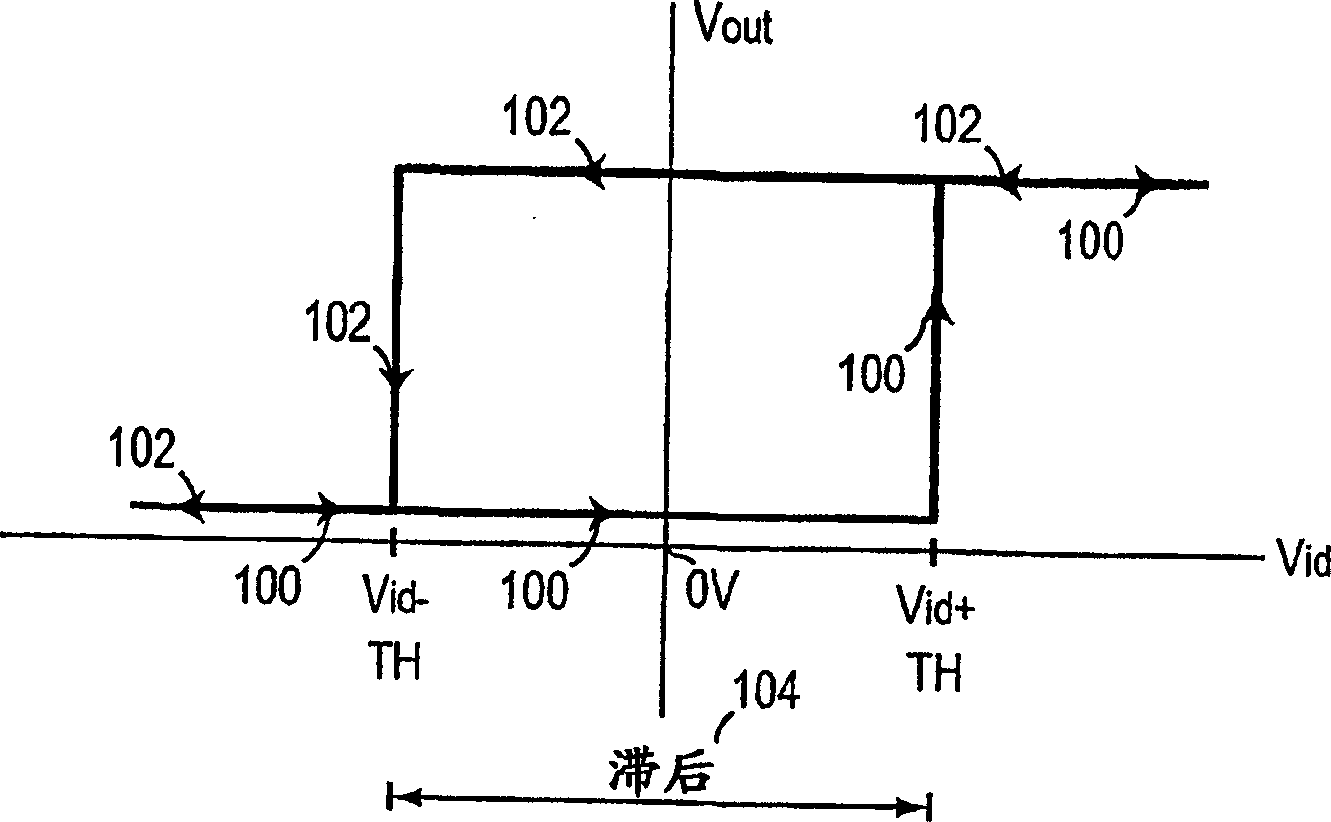
[0019] figure 1 shows the basic hysteresis curve found in virtually all differential signal receivers. The horizontal axis represents the positive differential signal Vid, and the vertical axis represents the output signal from 0 to +Vcc. A negative differential signal starting at 100 increases until the threshold Vid+ is reached, at which point the output goes high. Vid then travels in the negative direction 102 while the output remains high until the threshold Vid- is reached, at which point the output goes low. The difference between Vid+ and Vid- is the hysteresis 104 inherent in the circuit. The hysteresis is required due to the differential input sensitivity of the amplifier. Without hysteresis, if a signal falls within the input sensitivity region, the amplifier cannot accurately determine its state. If the signal stays in this undefined region, there is a possibility that the amplifier becomes unstable and oscillates. Additional hysteresis can be added by design t...


PUM


Abstract

A differential input failsafe circuit is disclosed that detects and signals a failsafe condition if a combination of a missing or too low differential signal and a frequency below a frequency limit is detected. The output signal from the fail-safe circuit is held in a given state which is an invalid representation of the differential input signal. Fail-safe conditions are detected using a frequency detector, complementary offset auxiliary amplifier with limited frequency roll-off. In addition, using a delay circuit requires that the fail-safe condition exists for a period of time before the fail-safe circuit is activated. Initialization circuitry ensures proper power-up conditions, enabling the circuitry to detect a fail-safe condition and, regardless of the previous state of the signal, ensure a reliable fail-safe.

Description

technical field [0001] This invention relates to logic differential amplifier circuits and, more particularly, to receivers incorporating failsafe circuits. Background technique [0002] A fail-safe differential amplifier or receiver provides a known output when an indeterminate or invalid input signal is present at the input. Invalid input signals typically occur when the input is floating or tri-stated or shorted. But partial shorts or opens can also cause invalid input signals. Faced with such an invalid input signal, the receiver will typically oscillate, turn on noise, or remain in an indeterminate state. [0003] Previous solutions have provided biasing resistors at the input of the differential receiver to bias the input to a known state by providing a DC offset at the input. However, such an offset may unbalance the returning currents, distorting the output and possibly loading and reducing the input signal amplitude. Other solutions have been to bias the input o...

Claims


Application Information

Patent Timeline
Patent Type & Authority Applications(China)
IPC IPC(8): H03F3/68
CPCH03F3/68H03F3/45
Inventor 普拉瓦斯·普拉丹
Owner FAIRCHILD SEMICON CORP
Why Eureka
Try Eureka