Ethernet performance measurement method, device and system

A measurement method and Ethernet technology, applied in the Internet field, can solve the problems of high complexity, affecting the accuracy of fault location, and many equipment resources.

Active Publication Date: 2018-10-30
中国兵器装备集团兵器装备研究所
View PDF6 Cites 0 Cited by
  • Summary
  • Abstract
  • Description
  • Claims
  • Application Information

AI Technical Summary

Problems solved by technology

[0005] First, multiple maintenance domains need to be configured, multiple performance test tasks need to be started, and each measurement node needs to involve the configuration of multiple test parameters. The configuration workload is heavy and time-consuming
[0006] Second, multi-domain measurements cannot guarantee that performance measurements are based on the same time base
Therefore, it is impossible to directly use the performance test data of multiple maintenance domains for comparative analysis in the same time period, which affects the accuracy of fault location.
[0007] Third, multi-domain measurement consumes a lot of system resources and affects the test specifications of the whole machine
When fault location is performed, performance test tasks in multiple maintenance domains need to be performed in parallel, which takes up a lot of equipment resources. For example, the measurement of packet loss rate requires MEP nodes to allocate 2 counters and use 2 access control lists (Access Control Lists) for each test task. , ACL) rules, the performance measurement of each segment of the network cannot be completed by configuring only one test task, which affects the maximum number of performance test instances supported by the device
[0008] To sum up, there are problems of low efficiency and high complexity in the end-to-end performance monitoring of Ethernet in the existing technology

Method used


Image

  • Ethernet performance measurement method, device and system
  • Ethernet performance measurement method, device and system
  • Ethernet performance measurement method, device and system

Examples


Embodiment Construction

[0138] The technical solutions of the present invention will be described in further detail below with reference to the accompanying drawings and embodiments.

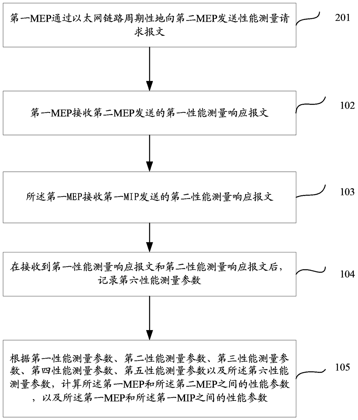
[0139] figure 1 A method for measuring Ethernet performance provided by the embodiment of the present invention, such as figure 1 As shown, the method includes:

[0140] 101. A first maintenance entity group endpoint MEP periodically sends a performance measurement request message to a second MEP through an Ethernet link, and the first MEP and the second MEP are respectively located at both ends of the Ethernet link , at least one maintenance entity group intermediate point (MIP for short) is set between the first MEP and the second MEP, and the performance measurement request message includes a first performance measurement parameter;

[0141] Generally, the endpoint of the maintenance entity group that initiates performance measurement is called the active end MEP, and the MEP that passively accepts performance mea...


PUM


Abstract

The invention provides a method for measuring performance of an Ethernet. The method comprises the following steps: sending a performance measurement request message to a second MEP by a first MEP, wherein the message comprises a first performance measurement parameter; receiving a first performance measurement response message sent by the second MEP, wherein the first performance measurement response message carries a third performance measurement parameter and a fourth performance measurement parameter; receiving a second performance measurement response message sent by a first MIP, wherein the second performance measurement response message carries a first performance measurement parameter, a second performance measurement parameter and a fifth performance measurement parameter; after receiving the first performance measurement response message and the second performance measurement response message, recording a sixth performance measurement parameter; calculating performance parameters between the first MEP and the second MEP and the performance parameters between the first MEP and the MIP according to the performance measurement parameters. By virtue of the method, device and system provided by the embodiment, measurement on packet loss, time delay and jitter performance of each node on a service path can be finished at a time and multiple times of measurement for subregions are not needed.

Description

technical field [0001] The invention relates to the Internet field, in particular to an Ethernet performance measurement method, performance measurement device and system. Background technique [0002] The Ethernet layer operation, administration, and maintenance (OAM) protocol developed by the International Telecommunications Union (ITU for short) provides fault management (fault management, FM for short) and performance monitoring (performance monitoring) , referred to as PM) two functions; it defines a series of methods for measuring packet loss, delay, and jitter of Ethernet packets, so that operators can obtain the service level agreement (service level agreement, SLA) of the network in real time, and discover network performance problem [0003] Although the OAM protocol defined by ITU-T solves the end-to-end performance measurement problem of Layer 2 Ethernet in point-to-point networking, it can realize the maintenance entity group endpoint (maintenance entity group,...

Claims


Application Information

Patent Timeline
Patent Type & Authority Patents(China)
IPC IPC(8): H04L12/26
Inventor 潘望王德义刘宏明
Owner 中国兵器装备集团兵器装备研究所
Why Eureka
Try Eureka