Blushless DC motor and blushless DC motor controller

A motor control and motor technology, which is applied in control systems, electromechanical devices, DC motor speed/torque control, etc., can solve the problems of not considering the influence of the bridge, and can not achieve high efficiency and low noise at the same time, and achieves the reduction of The effect of vibration

Inactive Publication Date: 2006-01-04
DAIKIN IND LTD
View PDF3 Cites 13 Cited by
  • Summary
  • Abstract
  • Description
  • Claims
  • Application Information

AI Technical Summary

Problems solved by technology

This is to suppress short-circuiting of magnetic flux as much as possible by making it as thin as possible, but it must be kept at a certain thickness or more in consideration of centrifugal strength, but the influence of the existence of bridges is not considered.
Therefore, high efficiency and low noise cannot be achieved at the same time

Method used


Image

  • Blushless DC motor and blushless DC motor controller
  • Blushless DC motor and blushless DC motor controller
  • Blushless DC motor and blushless DC motor controller

Examples


Embodiment Construction

[0063] Hereinafter, embodiments of a brushless DC motor and a brushless DC motor control device according to the present invention will be described in detail with reference to the drawings.

[0064] First, the reduction of noise and the determination of the angle θ 0 Methods.

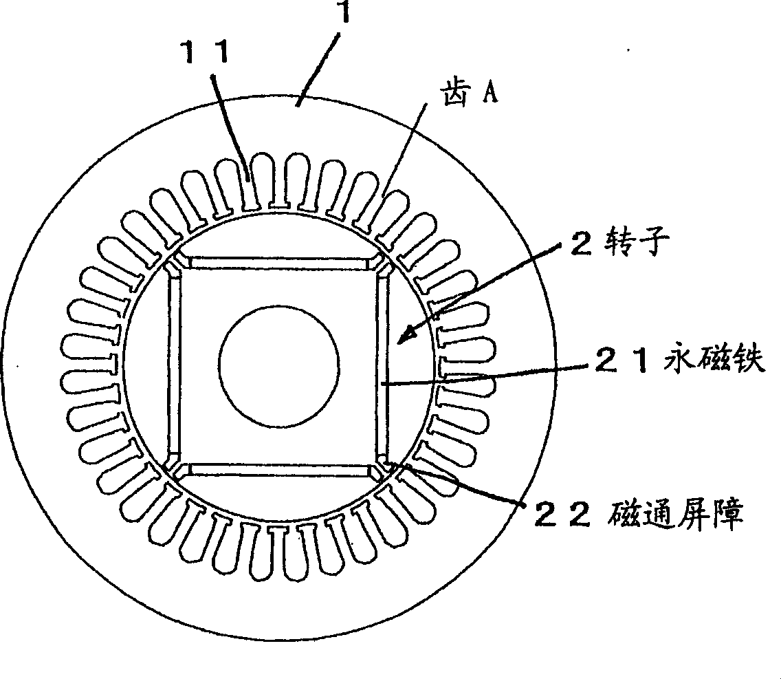
[0065] figure 1 It is a vertical cross-sectional view showing the structure of a conventional brushless DC motor, including a stator 1 formed with a plurality of teeth 11, and a permanent magnet 21 housed inside, and has a for extending from both ends of the permanent magnet 21 to the outer surface. The rotor 2 is protected by a barrier 22 which prevents short-circuiting of the magnetic flux.

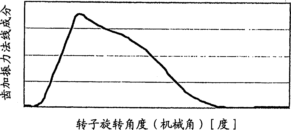
[0066] figure 2 It is a graph showing the vibration force (normal component) applied to the tooth A when a brushless DC motor having a rotor whose width of the barrier 22 is close to the thickness of the permanent magnet 21 is in operation.

[0067] From figure 2 It can be seen that as the rotor 2 rotates...


PUM


Abstract

Let (theta0) be the angle formed between the end on the magnetic pole center side of a magnetic flux barrier (22) and the end of an adjacent magnetic flux barrier (22) on the side contacting a rib 23 with respect to the rotor center, f be the oscillation frequency desired to be reduced, Pn be the number of pole pairs, f0 = Pn * N be the electric angle frequency, N be the motor rpm, m = 1, 3, 5,..., and thetar be the angle formed by ribs with respect to the rotor center. The angle is set such that the relation theta0 = 180 DEG * m / (Pn * f / f0), (where, 2 theta0 - thetar < 90 DEG ) is satisfied, whereby high efficiency and low noise can be easily made compatible.

Description

technical field [0001] The present invention relates to a brushless DC motor and a brushless DC motor control device, and more particularly to a brushless DC motor and a brushless DC motor control device capable of achieving both high efficiency and low noise. Background technique [0002] Conventionally, it has been proposed to increase the efficiency by setting the magnetic flux barrier so that the dimension in the circumferential direction exceeds the thickness of the magnet (see JP-A-2002-44888). [0003] In addition, in a brushless DC motor formed by embedding permanent magnets inside the rotor (hereinafter, abbreviated as IPM), it has been proposed to reduce the noise by adjusting the angle of the magnetic flux barrier (see JP-A-11-98731 Gazette, JP-A-2000-217287 Gazette) [0004] It has also been proposed to twist the lamination direction of the rotor in the IPM (see Patent No. 3028669). [0005] In a motor with the number of magnetic pole pairs Pn, at a frequency t...

Claims


Application Information

Patent Timeline
Patent Type & Authority Applications(China)
IPC IPC(8): H02K1/27H02P6/18H02K29/06H02K29/00H02K21/14H02K29/03
CPCH02K1/276H02K29/03H02K21/14H02P7/025
Inventor 西嵨清隆
Owner DAIKIN IND LTD
Why Eureka
Try Eureka