Power supply control method of diesel locomotive auxiliary driving electric system and its device

A technology for auxiliary transmission and electrical systems, applied in electric braking systems, collectors, electric vehicles, etc., can solve the problems of increased diesel engine speed, increased fuel consumption of diesel engines, and unreasonable problems, so as to save fuel, reduce fuel consumption, and reduce fuel consumption Effect

Active Publication Date: 2006-01-11
ZHUZHOU CSR TIMES ELECTRIC CO LTD
View PDF1 Cites 6 Cited by
  • Summary
  • Abstract
  • Description
  • Claims
  • Application Information

AI Technical Summary

Problems solved by technology

In the auxiliary transmission system of traditional diesel locomotives, when the locomotive implements resistance braking, the main generator will be isolated from the traction motor, and the traction motor will be converted from a motor to a generator for braking, and the electric energy generated by it will be consumed through the braking resistor , at this time the traction motor has a higher requirement on the ventilation rate, in order not to make the temperature of the traction motor too high, it is necessary to increase the ventilation rate to cool down, and the traction fan is usually powered by an auxiliary generator, the ventilation rate must be increased It is necessary to increase the speed of the traction fan, because the traction fan is powered by the auxiliary generator, so the speed of the traction fan is changed to the speed of the generator, the speed of the auxiliary generator must be increased, and then the driving force of the auxiliary generator to generate electricity must be increased. The speed of the diesel engine increases, that is to say, in order to ensure the ventilation volume of the traction motor under the condition of large braking current, the speed of the diesel engine can only be increased to ensure
However, the fuel consumption and speed of a diesel engine are in a parabolic relationship, increasing the speed of a diesel engine will inevitably lead to a large amount of fuel consumption
Therefore, when the locomotive implements resistance braking, on the one hand, the electric energy generated by the braking of the traction motor will be wasted, and on the other hand, in order to ensure the ventilation of the traction motor, the fuel consumption of the diesel engine must be increased, which is extremely unreasonable, and it is necessary to pay attention to this. Improve

Method used


Image

  • Power supply control method of diesel locomotive auxiliary driving electric system and its device
  • Power supply control method of diesel locomotive auxiliary driving electric system and its device

Examples


Embodiment Construction

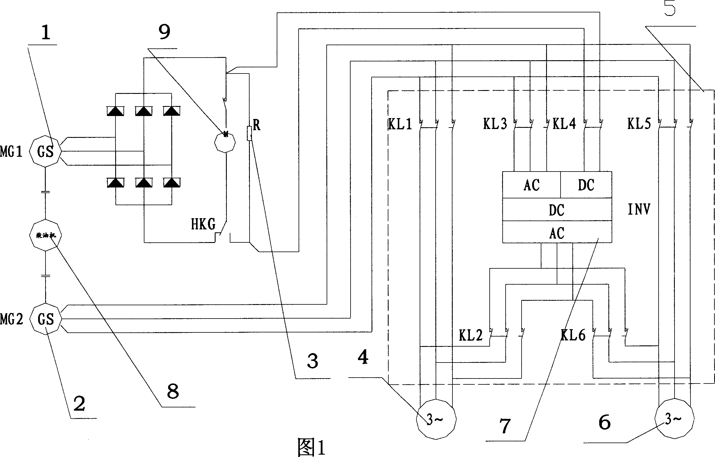
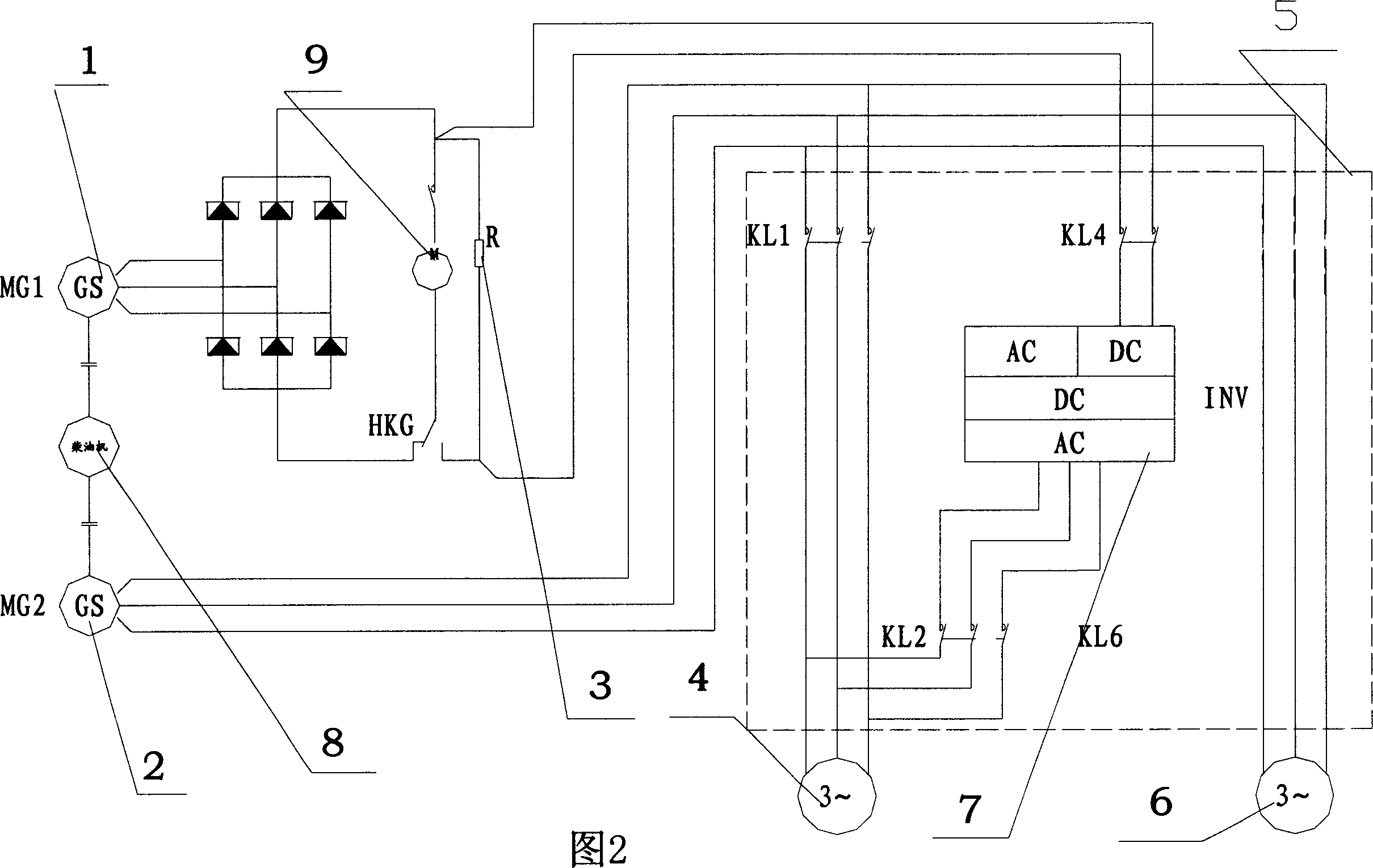
[0016] Accompanying drawing has provided the schematic diagram of electrical principle of the present invention, and the present invention will be further described below in conjunction with accompanying drawing.

[0017] As can be seen from the accompanying drawings, the present invention belongs to a power supply system for auxiliary transmission electric control of diesel locomotives, including a main generator 1, an auxiliary generator 2, a braking resistor 3, a traction extension unit 4, a diesel engine 8, a traction motor 9 and cooling fan6. An auxiliary converter control system 5 is added to the electrical system of the auxiliary transmission system, and when the traction motor is powered by the main generator of the auxiliary transmission system in the traction operating condition, both the traction fan 4 and the cooling fan 6 are powered by the auxiliary generator 2 , the cooling fan 6 can also be powered by the auxiliary converter 7, and the auxiliary converter 7 is ...


PUM


Abstract

An electric power supplying method and device of the electric system in the auxiliary transmission system for diesel locomotive features that when the locomotive is in tractive state, the tractive ventilator is electrically powered by secondary electric generator, when it is in brake state, the traction motor is isolated from primary electric generator and the motor is modified as electric generator, when the generated potential is more than 230 VDC, the tractive ventilator is electrically powered by secondary current transformer, and the cooling fan is electrically powered by either secondary electric generator or current transformer.

Description

technical field [0001] The invention belongs to a power-taking method for an electrical device, in particular to a power-taking control method for an electrical system in an auxiliary transmission system of a diesel locomotive. The invention also relates to a power-taking control device for the electrical system of the auxiliary transmission system of a diesel locomotive. Background technique [0002] Diesel locomotive auxiliary transmission system consists of diesel locomotive diesel engine, main generator, auxiliary generator, multiple traction fan units and multiple cooling fan units, among which the traction fan is mainly used to ensure the ventilation volume requirements of the traction motor during the working process of the locomotive. , while the cooling fan is mainly used to ensure the cooling water temperature requirements of the diesel engine during the working process of the locomotive. In the auxiliary transmission system of traditional diesel locomotives, when ...

Claims


Application Information

Patent Timeline
Patent Type & Authority Applications(China)
IPC IPC(8): B60L1/00B60L7/00
Inventor 王颖矅叶顶康刘伯太唐勇军罗凌波
Owner ZHUZHOU CSR TIMES ELECTRIC CO LTD
Why Eureka
Try Eureka