Deep cooling treatment method of high speed steel tool

A cryogenic treatment, high-speed steel technology, applied in heat treatment furnaces, heat treatment equipment, manufacturing tools, etc., can solve the problems of insignificant effect and high energy consumption, and achieve the effects of uniform distribution, energy saving, and increase in the number of dimples

Inactive Publication Date: 2006-01-11
大连理工模具研究所有限公司
View PDF0 Cites 25 Cited by
  • Summary
  • Abstract
  • Description
  • Claims
  • Application Information

AI Technical Summary

Problems solved by technology

[0004] The purpose of the present invention is to provide a cryogenic treatment process for high-speed steel cutting tools to solve the problems of large energy consumption and ineffective effects in the cryogenic treatment of high-speed steel cutting tools

Method used

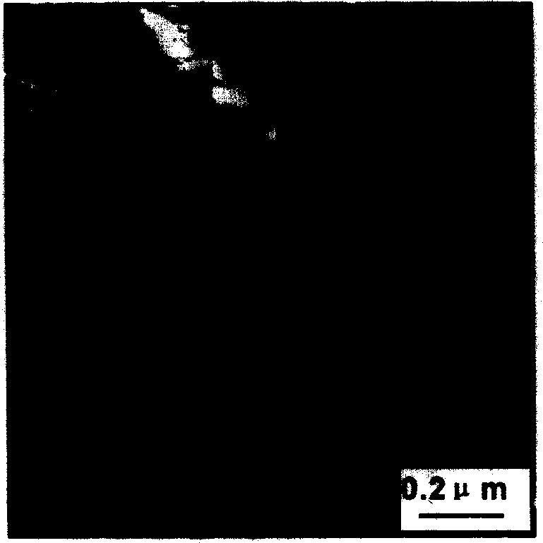
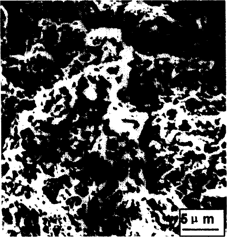

Image

  • Deep cooling treatment method of high speed steel tool
  • Deep cooling treatment method of high speed steel tool
  • Deep cooling treatment method of high speed steel tool

Examples


Embodiment Construction

[0022] The specific embodiments of the present invention will be described in detail below in conjunction with the technical solutions.

[0023] For W18Cr4V steel knives, the quenching temperature is 1280°C, oil quenching, tempering for 1 hour after quenching, the tempering temperature is 600°C, and cryogenic treatment is carried out in liquid nitrogen at -185~-196°C after tempering. Cryogenic treatment by liquid method. The cryogenic treatment process is as follows:

[0024] Step 1 Pre-cooling of tools before deep cooling

[0025] Put the tool on the liquid nitrogen surface to stay for 30 minutes, or quickly put 1 / 3 of the tool height into the liquid nitrogen without stopping and take it out immediately, repeating this for 2 to 3 times can also achieve the pre-cooling effect.

[0026] Step 2 Cryogenic insulation of the tool

[0027] Slowly put the pre-cooled tool into liquid nitrogen, and calculate the cryogenic holding time according to formula (1). Take 3 hours for the ...


PUM


Abstract

A deep cooling method for treating the cutting tool made of high-speed steel in order to elongate its service life includes such steps as quenching, tempering, precooling, deep cooling in liquefied N2 at -185--196 deg.C , holding the temp for a certain time calculated by an equation, recovering its temp to room temp and heating it in boiling water for 60 min. For the large cutting tool, said steps can be performed 2-3 times.

Description

technical field [0001] The invention belongs to the technical field of heat treatment technology for metal materials, and relates to the heat treatment of steel workpieces, in particular to a cryogenic treatment method for high-speed steel cutting tools. Background technique [0002] In the prior art, the cryogenic treatment process with better effect for high-speed steel cutting tools is: quenching + tempering once + deep cooling + tempering once, and the holding time of cryogenic treatment is the effective thickness or effective diameter of the workpiece multiplied by 5 ~8 minutes / mm, the direct immersion method of the liquid method is mostly used in cryogenic treatment. [0003] The problem existing in the current cryogenic treatment process of high-speed steel cutting tools is that there are many times of tempering and high energy consumption. The calculation of the cryogenic holding time in the cryogenic treatment process does not consider the incubation period of the ...

Claims


Application Information

Patent Timeline
Patent Type & Authority Applications(China)
IPC IPC(8): C21D9/22C21D1/18
Inventor 段春争李士燕王敏杰
Owner 大连理工模具研究所有限公司
Why Eureka
Try Eureka