Connecting element for a winding of an electric machine

A technology for wiring units and motors, applied to windings, electrical components, electric components, etc., to achieve the effects of reducing metal material costs, increasing efficiency, and saving waste cleaning costs

Inactive Publication Date: 2006-01-11
ROBERT BOSCH GMBH
View PDF1 Cites 26 Cited by
  • Summary
  • Abstract
  • Description
  • Claims
  • Application Information

AI Technical Summary

Problems solved by technology

Also contributes to saving on waste disposal costs due to virtually no material waste

Method used


Image

  • Connecting element for a winding of an electric machine
  • Connecting element for a winding of an electric machine
  • Connecting element for a winding of an electric machine

Examples


Embodiment Construction

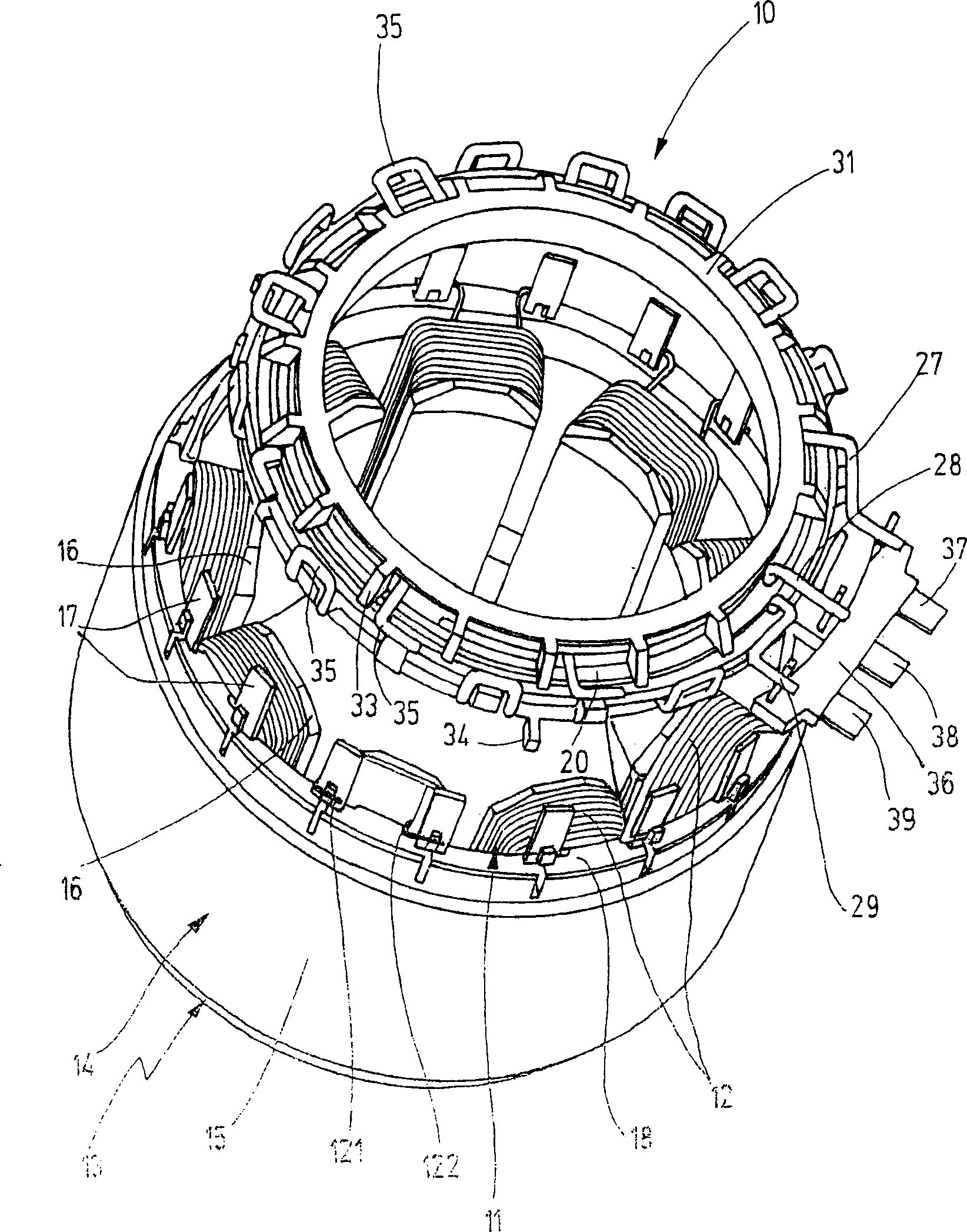
[0011] figure 1 The terminal unit 10 shown in top perspective view is designed for a three-phase winding 11 of nine coils 12 in total of a stator 13 of a brushless small motor, which can be an electronically commutated DC motor or synchronous motor. figure 1 The stator 13 shown in a perspective view has a stator body 14 which comprises, in a known manner, a hollow-cylindrical flux-conducting ring 15 and, in the exemplary embodiment, a total of nine stator teeth 16 projecting radially therefrom, These stator teeth and a rotor (not shown here) delimit the working air gap of the electric motor. An annular coil 12 is wound on each stator tooth 16 , and the coil ends 121 and 122 of each coil 12 are respectively connected to a connecting pin 17 . Viewed from the circumferential direction, the connection locks 17 are arranged equidistantly and protrude from the end face of the magnetic conduction ring 15 , and they are electrically insulated from the magnetic conduction ring 15 by ...


PUM


Abstract

The present invention provides an interconnection element for a multi-phase winding ( 11 ) that is comprised of coils ( 12 ) and belongs to an electric machine, in particular a brushless mini motor, having a support ( 20 ) made of insulating material and conducting strips that are disposed on the support ( 20 ) for producing interconnections among the coils ( 12 ). In order to reduce materials costs, the conducting strips are embodied in the form of bent wires ( 27 - 30 ) that are preferably contained in channels embodied in the support ( 20 ) and are fixed in place by means of two annular cover elements ( 31, 32 ) made of insulating material ( 1 ).

Description

[0001] The invention relates to a connection unit for a multiphase winding consisting of coils of an electric motor, in particular a brushless small electric motor according to the preamble of claim 1 . Background technique [0002] In a known connection element of this type (EP 1 062 720 B1), the support made of insulating material is a carrier plate, which supports the winding by means of a hub and a stator body formed as a laminated core are fixed together on a support tube which in turn is fixed on a motor flange. The busbars for establishing the connection between the coils are busbars fixed concentrically to the hub on the carrier plate, these busbars being produced as stamped parts. Among them, the first busbar is connected to the coil ends of all winding phases with its bent connecting piece to form a neutral point, and the other three busbars are concentrically fixed on the supporting plate around the first busbar, and the connecting piece is used for Connect to the ...

Claims


Application Information

Patent Timeline
Patent Type & Authority Applications(China)
IPC IPC(8): H02K3/52H02K5/22
CPCH02K5/225H02K3/522H02K2203/03H02K2203/09
Inventor C·克拉彭巴赫E·毛雷尔
Owner ROBERT BOSCH GMBH
Why Eureka
Try Eureka