Sealed type electric compressor
An electric compressor, hermetically sealed technology, used in machines/engines, liquid fuel engines, mechanical equipment, etc., can solve the problems of short working life, shape restriction of glass terminal pressure vessels, increase of signal lines, etc., to achieve effective heat transfer area The effect of enlargement, miniaturization and capability enhancement
- Summary
- Abstract
- Description
- Claims
- Application Information
AI Technical Summary
Problems solved by technology
Method used
Image

Examples
Embodiment 1
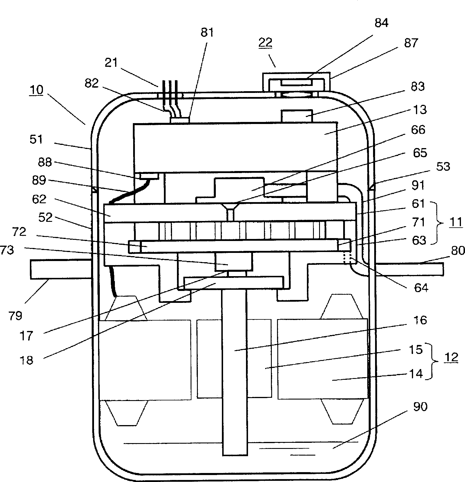
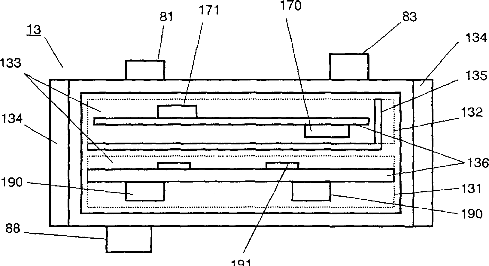
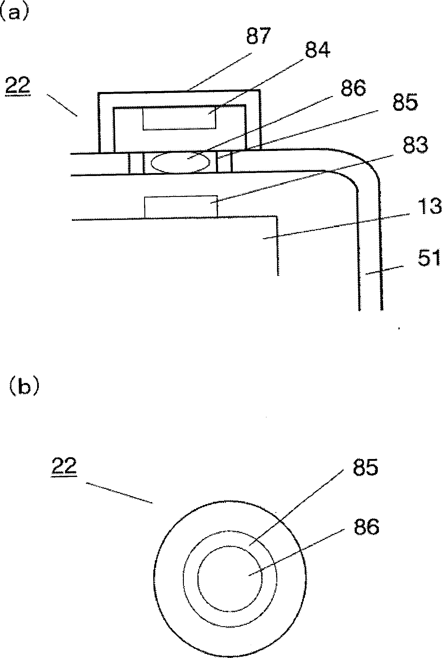
[0037] figure 1 It is a sectional view of the hermetic electric compressor in Embodiment 1 of the present invention, figure 2 is a sectional view showing the detailed structure of the motor drive assembly of the hermetic electric compressor, image 3 (a) is a sectional view showing the detailed structure near the communication device of the hermetic electric compressor, image 3 (b) is a plan view showing the detailed structure of the communication device of the hermetic electric compressor.
[0038] The sealed electric compressor 10 is a low-pressure compressor, and an upper casing 51 and a lower casing 52 form a sealed container. The airtight container is provided with: a compression part 11 , a motor 12 , and a motor drive assembly 13 . The motor driving assembly 13 is arranged at the uppermost part of the sealed container, and is used for supplying power to the motor 12 and controlling its operation. The upper case 51 and the lower case 52 are joined by a welding por...
Embodiment 2
[0055] pass below Figure 5 Next, a hermetic electric compressor according to Embodiment 2 of the present invention will be described. Here, the same reference numerals are used for the same components as those in Embodiment 1, and repeated description thereof will be omitted. In addition, since operations other than the communication device 22 are basically the same as those in the first embodiment, detailed description thereof will also be omitted.
[0056] Figure 5 It is a cross-sectional view of the detailed structure of the communication device 22 installed in the upper case 51 . In Embodiment 2 of the present invention, the communication method in the communication device 22 adopts the electromagnetic field signal method, which includes: an input and output terminal located on the side of the motor drive assembly 13 for sending / receiving control signals in the form of electromagnetic field signals That is, an internal transmission / reception terminal 93 ; an external tr...
Embodiment 3
[0061] pass below Figure 6 , 7 and 8 to describe the hermetic electric compressor in Embodiment 3 of the present invention. In Embodiment 3 of the present invention, the communication method of the communication device 22 adopts a vibration signal transmission method. Here, the same components as those in Embodiment 1 are denoted by the same symbols, and their repeated descriptions are omitted. In addition, since operations other than the communication device 22 are basically the same as those in the first embodiment, detailed description thereof will also be omitted.
[0062] Figure 6 A detailed cross-sectional view of the communication device 22 mounted on the upper case 51 in Embodiment 1 of Embodiment 3 is shown in . This communication device 22 comprises: can send / receive the input-output terminal (namely internal sending / receiving end) 103 of the motor drive assembly 13 of the control signal of vibration signal form, can send / receive the input-output terminal ( Th...
PUM
 Abstract
Description
Claims
Application Information
 - R&D
- Intellectual Property
- Life Sciences
- Materials
- Tech Scout
- Unparalleled Data Quality
- Higher Quality Content
- 60% Fewer Hallucinations
Browse by: Latest US Patents, China's latest patents, Technical Efficacy Thesaurus, Application Domain, Technology Topic, Popular Technical Reports.
© 2025 PatSnap. All rights reserved.Legal|Privacy policy|Modern Slavery Act Transparency Statement|Sitemap|About US| Contact US: help@patsnap.com