Module for projecting a light beam

A beam and light source technology, applied in the field of collimated beam modules, can solve the problems of low lighting efficiency

Inactive Publication Date: 2006-01-18
CENT RICERCHE FIAT SCPA
View PDF7 Cites 33 Cited by
  • Summary
  • Abstract
  • Description
  • Claims
  • Application Information

AI Technical Summary

Problems solved by technology

[0009] This configuration has the disadvantage of low illumination efficiency due to the presence of partitions that absorb a portion of the optical radiation focused by the polyellipsoidal reflector

Method used


Image

  • Module for projecting a light beam
  • Module for projecting a light beam
  • Module for projecting a light beam

Examples


Embodiment Construction

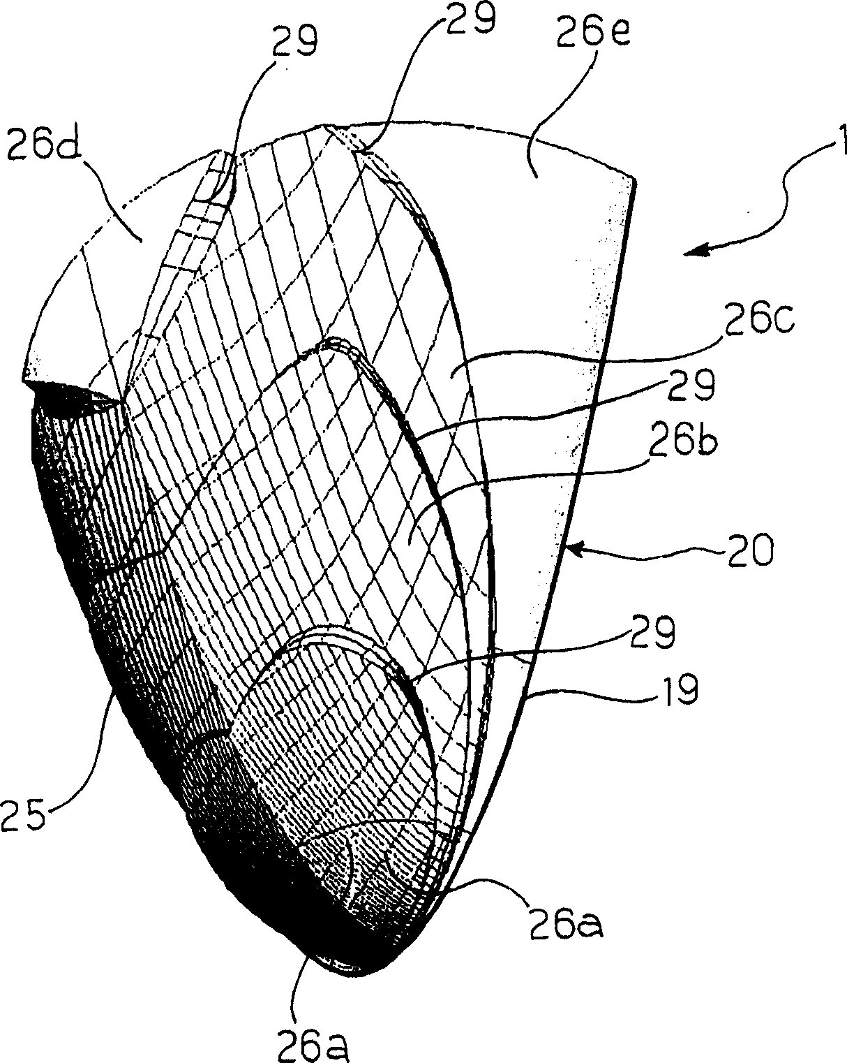
[0033] image 3 and Figure 4 A module for projecting a light beam according to the invention is shown. The module 1 comprises a light source 10 and an optical device 20 coupled to the light source 10 . For this purpose, the optical device 20 consists of a transparent dielectric body having:

[0034] i) a first face 19 coupled to a substantially planar support face 21 on which the light source 10 is arranged in such a way that the light source 10 emits light only in the direction of the optical device;

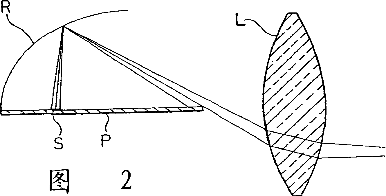
[0035] ii) A second curved reflective surface 25 with a concavity facing the support surface 21 . The reflective surface 25 is designed in such a way that at least some of the light from the light source 10 in a radially outward direction, represented by the light rays A, is reflected by the surface 25 into a different direction B, however, the direction B is different from the direction B of the supporting surface 21. The deviation from the parallel state is small. In ot...


PUM


Abstract

A module (1, 1', 1'', 1''') for projecting a light beam comprises a light source (10) and a substantially flat support surface (21, 21', 21'', 21''') on which the source is arranged in a manner such as to emit light from only one side of the surface, and means for reflecting the light emitted by the source. The reflecting means comprise a curved reflecting surface (25, 25', 25'', 25''') which extends on one side of the support surface, has a concavity facing towards the support surface, and can reflect the light coming from the source in a principal direction substantially parallel to the support surface of the source. An optical device for a module according to the invention and a vehicle front light assembly comprising a plurality of modules according to the invention form further subjects of the invention.

Description

technical field [0001] The invention relates to a module for collimating light beams of the type defined by the preamble of claim 1 . Background technique [0002] Modules of this type are known, for example US patent 4698730 discloses a module comprising LEDs mounted on a support with radial encapsulation and optical elements operating in total reflection. The optical element has a substantially cylindrical recess in which a lens serving as an LED package is housed. The device is characterized in that a part of the light emitted by the LED is collimated by a lens constituting its package, while another part of the light beam is collimated by a reflector of substantially parabolic cross-section. [0003] Other solutions like this are proposed, for example, in patent application WO 00 / 24062, where this collimation function is implemented with a transparent dielectric module housing the LED light source in a suitable, substantially cylindrical recess In; as in the preceding ...

Claims


Application Information

Patent Timeline
Patent Type & Authority Applications(China)
IPC IPC(8): F21S8/10F21V7/00F21V5/02F21V13/02F21W101/10B60Q1/04F21S8/12F21V7/06F21V7/09F21V13/04F21V17/00F21Y101/02
CPCF21V13/04F21V7/09F21S48/1163F21S48/137F21S48/1388F21S48/1159F21V7/0091F21Y2101/02F21S48/1241F21Y2115/10F21S41/155F21S41/24F21S41/255F21S41/336F21S41/36F21S41/148F21S41/151
Inventor P·雷佩托S·贝尔纳D·博利亚D·卡佩洛
Owner CENT RICERCHE FIAT SCPA
Why Eureka
Try Eureka