
Gray mask and method for manufacturing gray mask

A gray-tone mask and mask technology, which is applied in the photoengraving process of the pattern surface, the manufacture of semiconductor/solid-state devices, and the original for photomechanical processing, etc. Less than the gray tone mask and other problems, to achieve the effect of good graphics accuracy

Inactive Publication Date: 2006-01-18
HOYA CORP
View PDF2 Cites 4 Cited by
  • Summary
  • Abstract
  • Description
  • Claims
  • Application Information

AI Technical Summary

Problems solved by technology

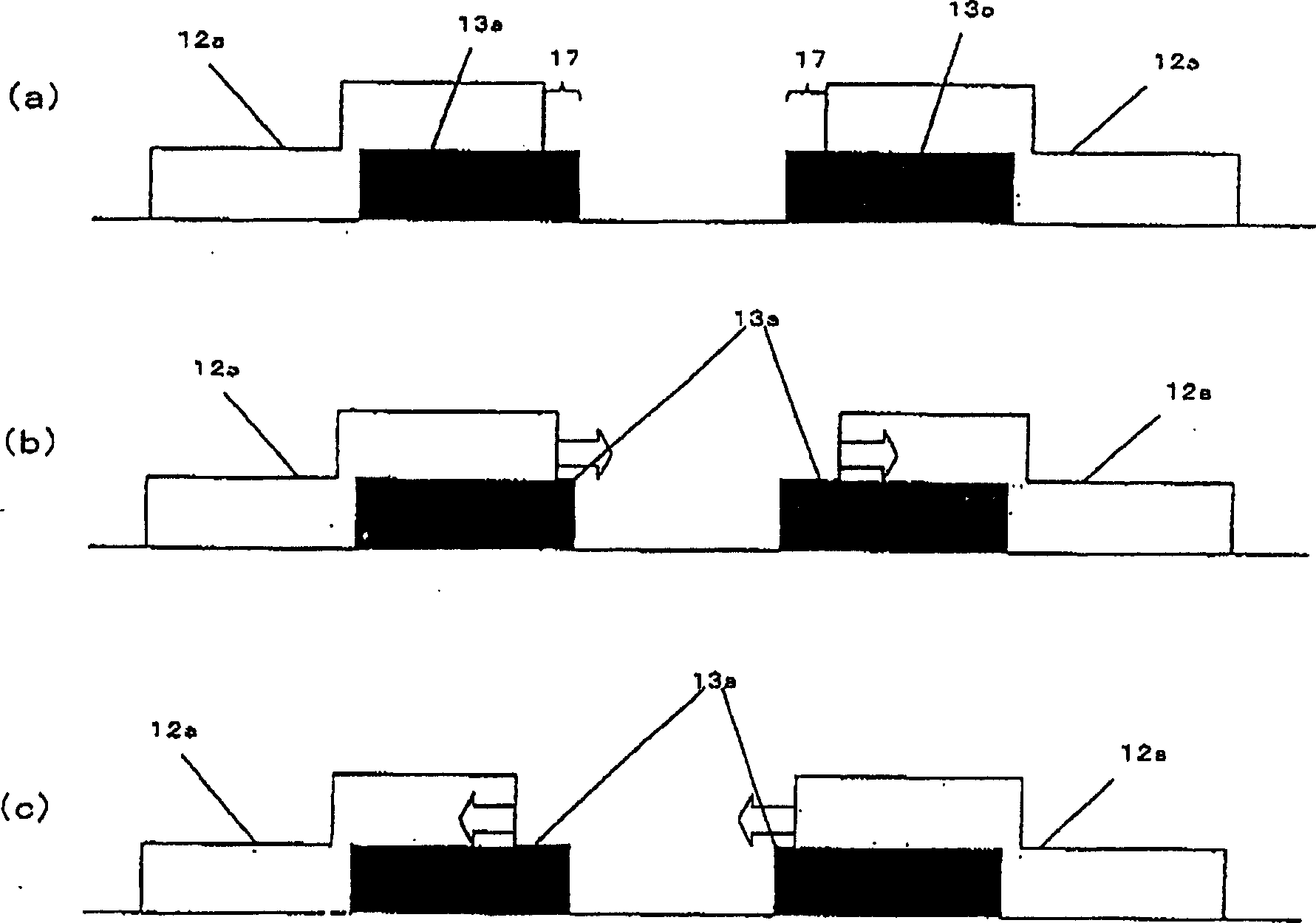
As shown in this example, when the position of the semi-transparent part is shifted from side to side, the width of the light-transmitting part 205 corresponding to the channel part becomes different from the design value, and the characteristics of the TFT substrate change.
In this way, there is a problem that it is often impossible to obtain a gray-tone mask that can form the channel part, which is particularly important for TFTs, with high precision.

Method used


Image

  • Gray mask and method for manufacturing gray mask
  • Gray mask and method for manufacturing gray mask
  • Gray mask and method for manufacturing gray mask

Examples


Embodiment Construction

[0072] Hereinafter, the present invention will be described in detail through embodiments.

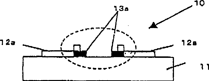
[0073] figure 1 It is a cross-sectional view showing the vicinity of a source electrode and a drain electrode on a TFT substrate of a gray tone mask according to Embodiment 1 of the present invention, figure 2 (a) is figure 1 Enlarged view of the part surrounded by the dashed line in .

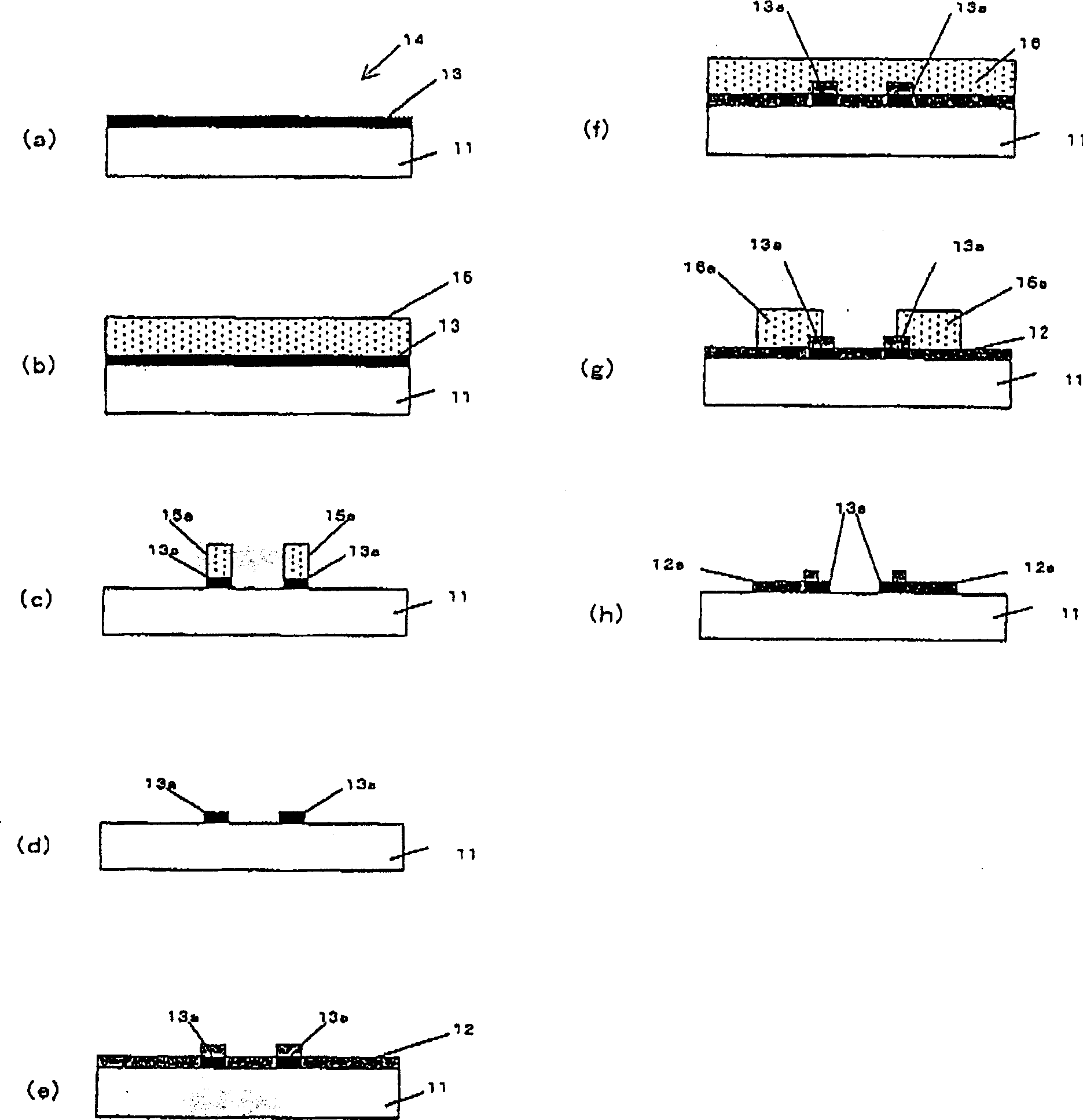
[0074] like figure 1 and figure 2 As shown, in this embodiment, on the transparent substrate 11 such as quartz, as the opposing portion of the source electrode and the drain electrode, a light-shielding film pattern 13a is formed in the region adjacent to the channel portion, and the source electrode and the drain electrode are connected to the channel portion. In the adjacent part of the track part, except for the margin region 17 on the electrode side, the region on the light-shielding film and the source electrode and the drain electrode part are formed with a semi-transparent film pattern ...


PUM

PropertyMeasurementUnit
transmittivityaaaaaaaaaa

Abstract

PROBLEM TO BE SOLVED: To provide a gray tone mask having preferable transmittance distribution in a semitransmitting part, a preferable pattern cross sectional form of a light shielding part adjacent to a light transmitting part, and preferable pattern accuracy of a light transmitting part as a gray tone mask having a pattern including a light transmitting part, a light shielding part and a semitransmitting part successively arranged in this order in one direction, and to provide a method for manufacturing the gray tone mask. ŽSOLUTION: The gray tone mask 10 has a pattern comprising a light shielding part, a light transmitting part and a semitransmitting part. The pattern includes a pattern having a light transmitting part, a light shielding part and a semitransmitting part successively arranged in this order in one direction. The light shielding part comprises layers of the light shielding film 13a forming the light shielding part and the semitransmitting film 12a formed in a region excluding a desired margin region in the side of the light shielding part in the border portion of the light transmitting part on the light shielding film 13a. Ž

Description

technical field [0001] The present invention relates to a method for producing a gray-tone mask suitably used for a thin film transistor substrate (hereinafter referred to as a TFT substrate) used in the production of a thin film transistor liquid crystal display device (Thin Film Transistor Liquid Crystal Display). Background technique [0002] Compared with CRTs (cathode ray tubes), TFT-LCDs have the advantages of being easy to form thin and low power consumption, and commercialization is rapidly progressing at present. The TFT-LCD has a TFT substrate in which TFTs are arranged on each pixel arranged in a matrix, and a color filter layer in which red, green, and blue pixel patterns are arranged corresponding to each pixel, and are superimposed on each other with a liquid crystal phase interposed therebetween. together the schematic structure. In the TFT-LCD, there are many manufacturing steps, and 5 to 6 photomasks are used only for the manufacture of the TFT substrate. ...

Claims


Application Information

Patent Timeline
Patent Type & Authority Applications(China)
IPC IPC(8): G02F1/136H01L21/027G03F7/20G03F1/54H01L21/336H01L29/786
CPCG02F1/133788G02F1/13394G02F1/1362G03F1/32G03F1/54H01L29/786
Inventor 佐野道明
Owner HOYA CORP
Learn More