Coaxial connector with RF switch

A coaxial connector and switch technology, applied in the direction of connection, two-pole connection, two-part connection device, etc., can solve the problems of low assembly productivity, shortened service life, loss of elasticity, etc., to improve assembly productivity, maintain stability, improve The effect of productivity

Inactive Publication Date: 2006-01-18
HTEC
View PDF1 Cites 13 Cited by
  • Summary
  • Abstract
  • Description
  • Claims
  • Application Information

AI Technical Summary

Problems solved by technology

[0004] However, with the miniaturization of mobile phones, the size of the above-mentioned conventional coaxial connectors has also been extremely miniaturized.
When assembling the ultra-small coaxial connector, by fitting the separately formed movable terminal and fixed terminal into the groove or hole in the insulating case, when the surface mounting is carried out on the circuit board after assembly, the flux It flows into the terminal side through the groove of the insulating case and the gap between the terminals, causing poor contact between the terminals.
In addition, since it is very difficult to assemble extremely small parts, the incidence of poor contact increases, which increases the number of assembly man-hours and reduces assembly productivity.
[0005] Moreover, the above-mentioned conventional coaxial connector such as figure 1 As shown, since the fixed terminal 104 supports the elastic part 108 fixed in a bent state with a relatively large bending angle ("" shape) at the insulating shell 109, when the central conductor 111 of the coaxial plug 110 is stressed to perform the switching action , due to the repeated large stress on the bending part, it has the disadvantage of being easy to lose elasticity and shorten the service life

Method used


Image

  • Coaxial connector with RF switch
  • Coaxial connector with RF switch
  • Coaxial connector with RF switch

Examples


Embodiment Construction

[0032] best practice

[0033] Hereinafter, embodiments of the coaxial connector of the present invention will be described in detail with reference to the accompanying drawings.

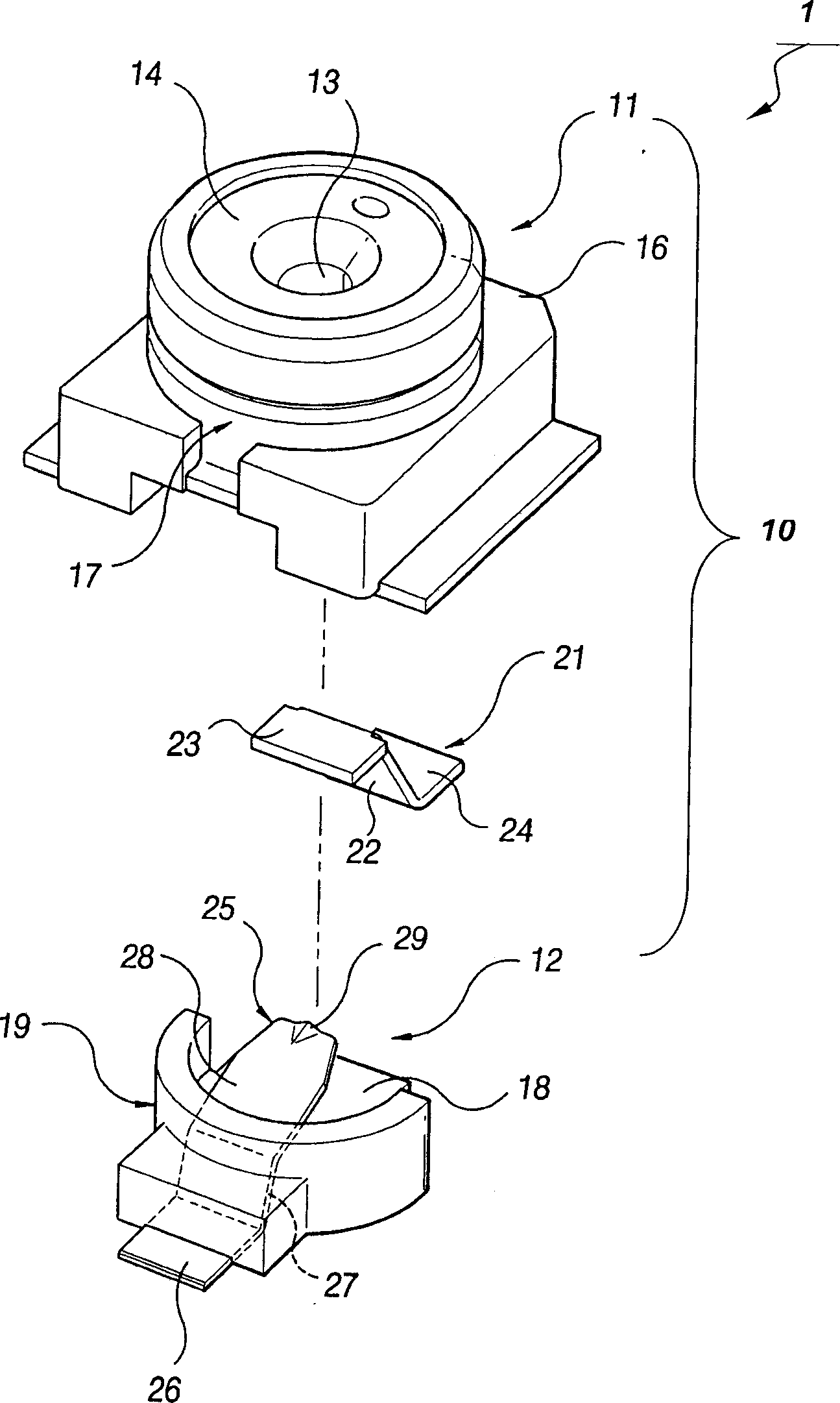
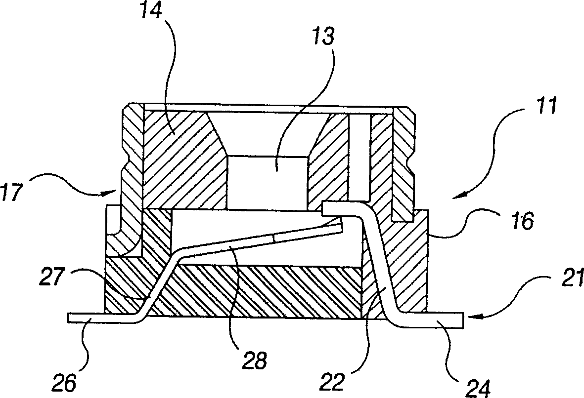
[0034] figure 2 is an exploded perspective view of the coaxial connector of the present invention, image 3 It is a combined cross-sectional view of the coaxial connector of the present invention. As shown in these figures, the coaxial connector 1 of the present invention includes a housing 10, an external conductor 17 covered on the outside of the housing 10, and is arranged on a circuit board of a communication terminal device such as a mobile phone for switching RF signals. The switching mechanism 20 of the circuit.

[0035] The casing 10 includes an upper case 11 and a lower case 12, which are combined into an approximately cylindrical shape. The upper housing 11 includes an upper insulator 14 and an enclosure portion 16 . In the upper insulator 14, as figure 2 and Figure 4 The central ...


PUM


Abstract

The present invention relates to coaxial connector with an RF switch. In particular, a housing 10 covered with an external conductor 17 is composed of upper and lower housings 11 and 12 . A fixed terminal 21 connected to an RF circuit is insert molded in the upper housing 11 , and a movable terminal 25 that is selectively brought into contact with the fixed terminal 21 is insert molded in the lower housing 12 . The movable terminal 25 comprises a fixed portion 26 fixed to the lower housing 12 ; a waist portion 27 extending upwardly from the fixed portion 26 at a first angle alpha1 and molded to the lower housing 12 ; and an elastic piece 28 bent from the tip end of the waist portion 27 at a second angle alpha2, extending into a space 15 of the housing, and being contact with the fixed terminal 21.

Description

technical field [0001] The present invention relates to a coaxial connector, more specifically, to a circuit board with a mobile phone (handset) that can cut off radio frequency (RF) when assembling a central conductor of a plug connector. Coaxial connector for the switch of the loop. technical background [0002] In portable communication devices such as mobile phones, coaxial connectors equipped with RF switches for checking high-frequency circuits are used. An example of such a coaxial connector with an RF switch can be found in Japanese Patent Laid-Open No. 2003-123915. [0003] The conventional coaxial connector 100 such as figure 1 As shown, it includes an insulating housing 102 having a hole 101 that can be inserted by a central conductor 111 of a coaxial plug 110, an outer conductor 103 disposed outside the insulating housing 102, and a fixed terminal 104 disposed below the hole 101 of the insulating housing 102 and the movable terminal 105. The fixed terminal 10...

Claims


Application Information

Patent Timeline
Patent Type & Authority Applications(China)
IPC IPC(8): H01R24/02H01R13/703H01R12/00
CPCH01R24/46H01R2103/00H01R24/50H01R13/646
Inventor 吕运哲
Owner HTEC
Why Eureka
Try Eureka