
Digital TV channel deducing device

A technology for inferring devices and channels, applied in the field of digital TV, can solve the problems of poor performance of simultaneous multi-channel reception, inability to activate the beating integration filtering tail of the transmitting end, showing weak characteristics, etc.

Inactive Publication Date: 2006-01-18
LEJIN GUANGDIAN ELECTRONIC CO LTD SHANGHAI
View PDF0 Cites 0 Cited by
  • Summary
  • Abstract
  • Description
  • Claims
  • Application Information

AI Technical Summary

Problems solved by technology

[0029] In order to cancel the data image contained in the channel impulse response (CIR), because of the characteristic of moving average, the equalizer for the time domain updated in symbol units in the video channel shows very weak characteristics
[0030] At the same time, when in the limit method, even the channel impulse response (CIR) value exceeding the critical value cannot activate the filter tail of the jitter integration filter (pulse sharing filter) at the transmitting end and the integrated filtering (matched filter) at the receiving end, and Severe performance overheating occurs
[0031] In addition, the actual DTV terrestrial frequency reception environment, even if the reception environment is good, still has frequency spectrum fluctuations to some extent. When these channel derivation devices are used in DTV receivers, there will be synchronous multiple channels (dynamic multipath channel) The poor reception performance of the

Method used


Image

  • Digital TV channel deducing device
  • Digital TV channel deducing device
  • Digital TV channel deducing device

Examples


Embodiment Construction

[0048] The present invention will be described in detail below with reference to the accompanying drawings.

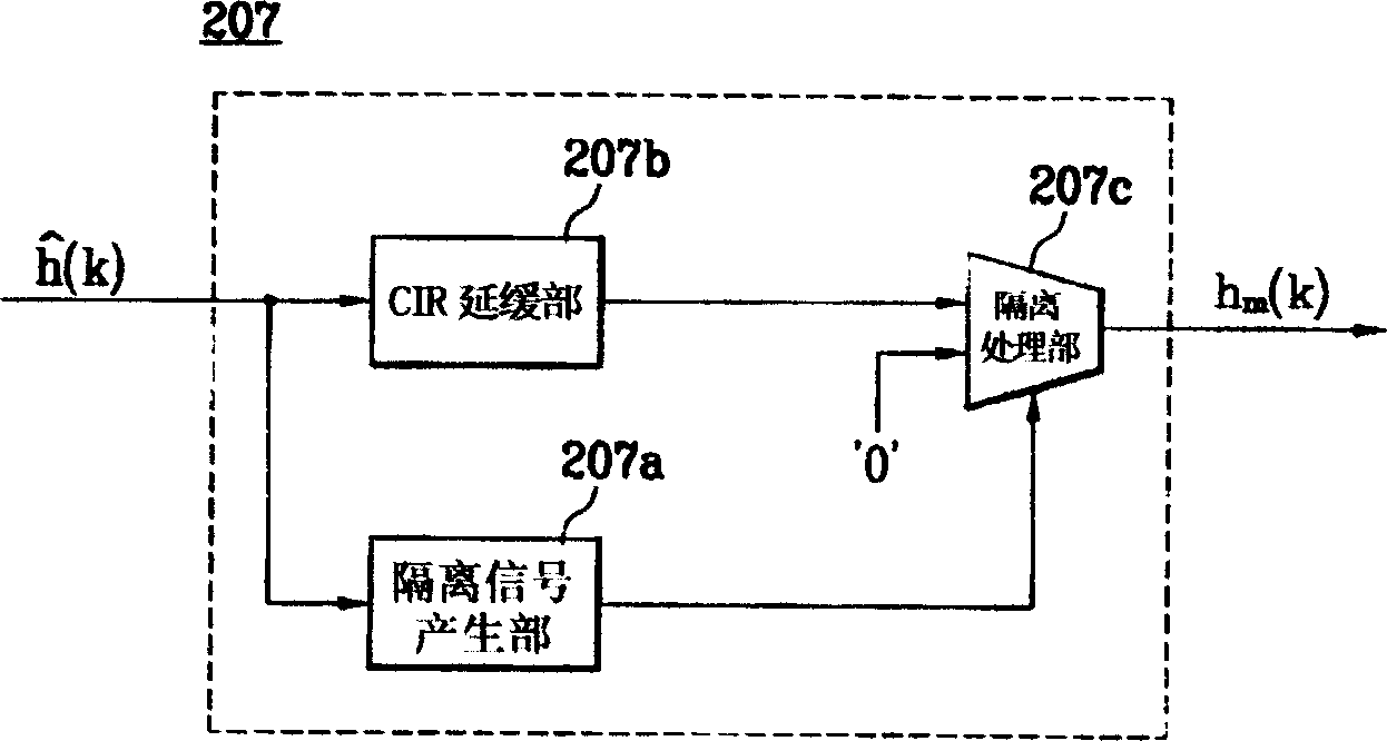
[0049] figure 2 is a structural diagram of a channel derivation device according to the present invention, image 3 is displayed figure 2 Block diagram of the Channel Impulse Response (CIR) Isolation section of .

[0050] Such as figure 2 As shown, the channel derivation device according to the present invention is to output the training sequence (Training Sequence) 201 of the training interval signal; obtain the cross-correlation value of the terrestrial frequency TV signal (y(n)) received from the outside and the above-mentioned training interval signal Cross Correlator (Cross Correlator) 202 of (P(i)); among the cross-correlation values ​​(P(i)) output by the above-mentioned cross-correlation value 202, the value used when acquiring the actual channel response (CIR) Each environment will only appear once, and the cross-correlation value maximum search unit (M...


PUM


Abstract

This invention relates to a presumption device of digital TV channel, which comprises a correlative value generating part, used for getting base belt signal and the signal during train; a correlative value maximum hunting part used in the pulse of the actual channel; the correlative value guidance generating part, used for outputting the correlative guidance corresponding to the CIR assigned range; the memory, used for outputting the self correlative value array of the train range signal; the computing part, used for computing the CIR assigned value with the correlative value radio guidance and the array of the self correlative value; the CIR separating part, used for removing the noise in the CIR assigned value.

Description

technical field [0001] The present invention relates to digital TV, in particular to a digital TV channel derivation device capable of inferring a more accurate impulse response of a specified channel in a video channel. Background technique [0002] The terrestrial frequency TV signal transmitted in 8 VSB (Vestigial Side Band) mode reaches the receiving end through dynamic multi-path channels. Since the arriving signal is seriously interfered by adjacent signals, in order to restore the original signal, it is inevitable to use an equalizer. [0003] At present, the receiver of a single feedback frequency transmission system similar to the VSB method uses equalizers most of the time, and the most representative one is the nonlinear decision feedback equalizer (Decision Feedback Equalizer: DEF below). [0004] The above-mentioned equalizer adopts the least-mean-squares (LMS; least-mean-squares) method. Although it has the advantage of being simple, when the interference phen...

Claims


Application Information

Patent Timeline
Patent Type & Authority Applications(China)
IPC IPC(8): H04N5/44H04N5/50
Inventor 金哉亨洪性龙
Owner LEJIN GUANGDIAN ELECTRONIC CO LTD SHANGHAI
Learn More