
Structure for installing drainage disk of indoor machine of air conditioner

An air-conditioning indoor unit and installation structure technology, which is applied in air-conditioning systems, condensate prevention, space heating and ventilation, etc., can solve the problems of condensate leakage, sloshing, poor installation strength of heat exchanger 60, etc., and achieve improved stability performance, anti-shake effect

Inactive Publication Date: 2006-02-01
LG ELECTRONICS (TIANJIN) APPLIANCES CO LTD
View PDF0 Cites 4 Cited by
  • Summary
  • Abstract
  • Description
  • Claims
  • Application Information

AI Technical Summary

Problems solved by technology

[0011] The above prior art drain pan 80 and heat exchanger 60 are separated after installation. Due to the error of the installation process, the drain pan 80 cannot accurately accommodate the condensed water of the heat exchanger 60, causing the condensed water to leak out; in addition, the heat exchanger 60 The installation strength is poor, resulting in shaking

Method used


Image

  • Structure for installing drainage disk of indoor machine of air conditioner
  • Structure for installing drainage disk of indoor machine of air conditioner
  • Structure for installing drainage disk of indoor machine of air conditioner

Examples


Embodiment Construction

[0044] Embodiments of the present invention will be described in detail below in conjunction with the accompanying drawings.

[0045] Figure 4 It is a front perspective schematic diagram of the air conditioner indoor unit of the present invention; Figure 5 It is a three-dimensional schematic view of the back side of the air conditioner indoor unit of the present invention.

[0046] Such as Figure 4 , Figure 5 As shown, the appearance of the air conditioner indoor unit 100 of the present invention includes: a front panel 110 forming a front cover; The discharge port opening and closing device 600 between them; the discharge port opening and closing device 600 is connected to the discharge port door 650 for opening and closing the discharge port 121; the rear cover 200 is combined with the front frame 120 to form a back cover; it is located in the air-conditioned room On the lower side of the machine, the piping cover 190 for various pipelines of the air-conditioning ind...


PUM


Abstract

The present invention discloses a water drain tray mounting structure of air conditioner indoor machine. Said structure includes the following components: a rear cover, at least its one side face is equipped with an air inlet, in its lower end at least a connecting projection and a connecting baffle plate with connecting member through groove are formed, a heat exchanger which is mounted in front of inside of rear cover and its external peripheral surface has condensed water and a water drain tray which is mounted in front of inside of rear cover for collecting condensed water of heat exchanger and has a certain depth.

Description

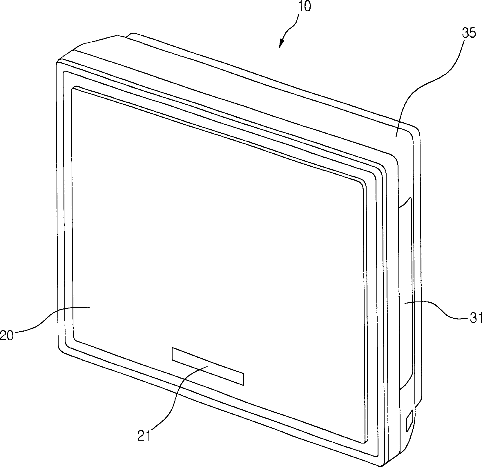
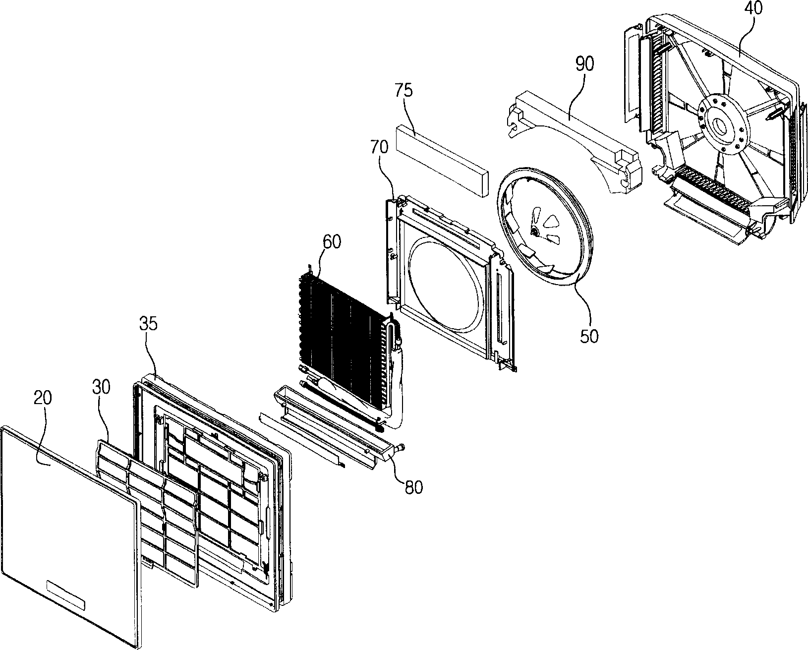
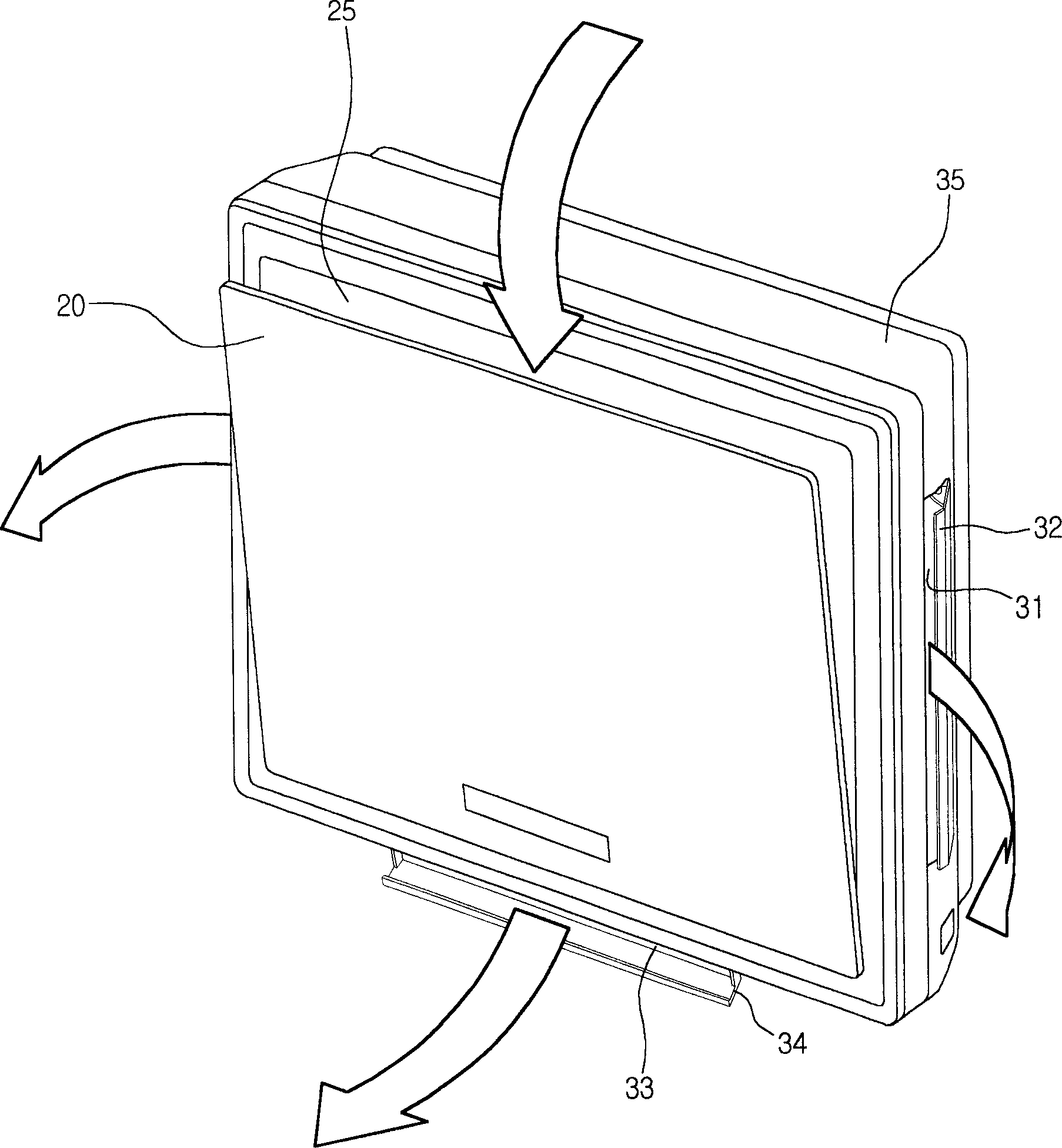
technical field [0001] The invention relates to an air conditioner indoor unit, in particular to a drain pan installation structure of the air conditioner indoor unit. Background technique [0002] figure 1 is a schematic diagram of an air conditioner indoor unit in the prior art; figure 2 It is a three-dimensional exploded view of an air conditioner indoor unit in the prior art; image 3 It is a schematic diagram of the air flow path of the air conditioner indoor unit in the prior art. [0003] refer to Figure 1 to Figure 3 , the prior art air conditioner indoor unit 10 comprises: the front panel 20 of the display part 21 that receives the signal of the remote controller to display the working state; contacts with the suction room air on the front panel 20 upper side, filters the foreign matter in the air filter 30; installs the filter 30 and the front panel 20 form the front frame 35 of the front part; the heat exchanger 60 that reduces the temperature of the air pur...

Claims


Application Information

Patent Timeline
IPC IPC(8): F24F13/22F24F1/00
Inventor 朴泰俊
Owner LG ELECTRONICS (TIANJIN) APPLIANCES CO LTD
Learn More