Solenoid operator and solenoid-operated switching device and control device for electromagnet

A switchgear, electromagnetic operation technology, applied in the direction of switchgear, switchgear components, electric switches, etc., can solve the problem of not being able to form a circuit breaker command

Active Publication Date: 2006-02-01
HITACHI IND EQUIP SYST CO LTD
View PDF2 Cites 14 Cited by
  • Summary
  • Abstract
  • Description
  • Claims
  • Application Information

AI Technical Summary

Problems solved by technology

[0009] However, there are still a large number of old analog relays as relays that output an opening command to the circuit breaker, and when an electromagnetically operated

Method used


Image

  • Solenoid operator and solenoid-operated switching device and control device for electromagnet
  • Solenoid operator and solenoid-operated switching device and control device for electromagnet
  • Solenoid operator and solenoid-operated switching device and control device for electromagnet

Examples


Embodiment Construction

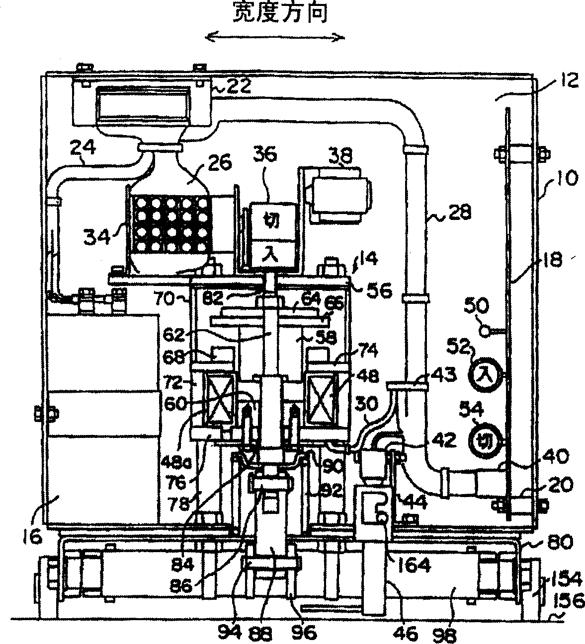
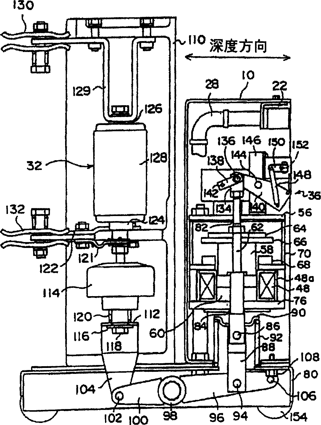
[0053] Next, an embodiment of the present invention will be described with reference to the drawings. figure 1 is a front view of the electromagnetic operating device of the present invention, figure 2 It is a side view of a solenoid-operated switchgear including a solenoid-operated device and a circuit breaker. exist figure 1 with figure 2 Among them, the electromagnetic operating device has a box-shaped casing 10, the casing 10 has an opening 12 on the front, and a front cover (omitted in the figure) is detachably fixed on the front of the casing 10. In the housing 10, a capacitor 16 and a control circuit board 18 are independently arranged with the electromagnet 14 as the center, the electromagnet 14 is fixed at the central position of the housing bottom with bolts and nuts, and the capacitor 16 and the control circuit board 18 are respectively fixed on on opposite sides of the housing. That is, the capacitor 16 is fixed on the left side of the housing 10 with bolts...


PUM


Abstract

The invention relates to an electromagnetic operating device and an electromagnetic operating type switching device and an electromagnet control device, in particular to the electromagnetic operating device capable of operating the switches like a breaker through an electromagnetic force and the electromagnetic operating type switching device and the electromagnet control device for driving an electromagnet which serves as the driving source of a drive switch. The designing structure of the invention capable of improving the operationability is that: the electromagnet (14) is arranged in the lower center position of a casing (10); a capacitor (16) and a control circuit board (18) are respectively arranged on the two sides of the electromagnet (14); an auxiliary contact (34), a display panel (36) and a counter (38) are arranged on the upper part of the electromagnet (14); the auxiliary contact (34), the display panel (36) and the counter (38) are further assembled on a board (56), thereby integrating with the electromagnet into a whole; thus, the capacitor (16) and the control circuit board (18) can be pulled out from the front.

Description

[0001] This application is a divisional application of the invention application with the application number 200310103229.2, the application date is October 28, 2003, and the invention name is "electromagnetic operation device, electromagnetic operation switch device and electromagnet control device". technical field [0002] The present invention relates to an electromagnetic operating device, an electromagnetic operating switch device, and an electromagnet control device, and more particularly to an electromagnetic operating device and an electromagnetic operating switch device for operating a switch such as a circuit breaker by using electromagnetic force, and controls as a driving source for driving a switch. Solenoid control device for electromagnet drive. Background technique [0003] When operating a switch such as a circuit breaker, the electromagnetic force generated by the electromagnet can be utilized to operate (refer to the 2nd-4th pages of the patent document Ja...

Claims


Application Information

Patent Timeline
IPC IPC(8): H01H3/28H01H9/54H01F7/06H01F7/18H02B11/10H01H33/28H01H33/38H01H33/40H01H33/42H01H33/46H01H33/53H01H33/59H01H33/66H02B11/127H02B11/133
Inventor 薮雅人记井智之森田步中泽彰男川上久雄品川拓实杉野友启藤田康信中村满椎名贵嗣佐藤贞男小笠原健一矶野聪土屋贤治桥本利夫阿部圭介小山健二福地正博
Owner HITACHI IND EQUIP SYST CO LTD
Why Eureka
Try Eureka