Eureka AIR delivers breakthrough ideas for toughest innovation challenges, trusted by R&D personnel around the world.

Refrigeration system with bypass subcooling and component size de-optimization

A refrigeration system and component technology, applied in the field of high-efficiency refrigeration systems, can solve the problems of small improvement of mixed refrigerants, high-pressure performance, and limited practical attention, and achieve the effects of improving EER, reducing space, and reducing system costs

Inactive Publication Date: 2006-02-08
沃特克斯·埃尔康公司
View PDF6 Cites 13 Cited by
  • Summary
  • Abstract
  • Description
  • Claims
  • Application Information

AI Technical Summary

Problems solved by technology

[0014] But in both cases the beneficial effects of a single refrigerant system were not obtained, but for their first approach they found an improvement over zeotropic refrigerants
But for their second method (the first method of Kite et al. patent), they did not improve the mixed or single refrigerant system
[0015] Furthermore, the reported improvement over mixed refrigerants is minimal, and since mixed refrigerants are not commercially exploited, and since such refrigerants require higher pressure performance than systems using single refrigerants, in any case, There are limits to how much people actually pay attention to them now

Method used


Image

  • Refrigeration system with bypass subcooling and component size de-optimization
  • Refrigeration system with bypass subcooling and component size de-optimization
  • Refrigeration system with bypass subcooling and component size de-optimization

Examples


Embodiment Construction

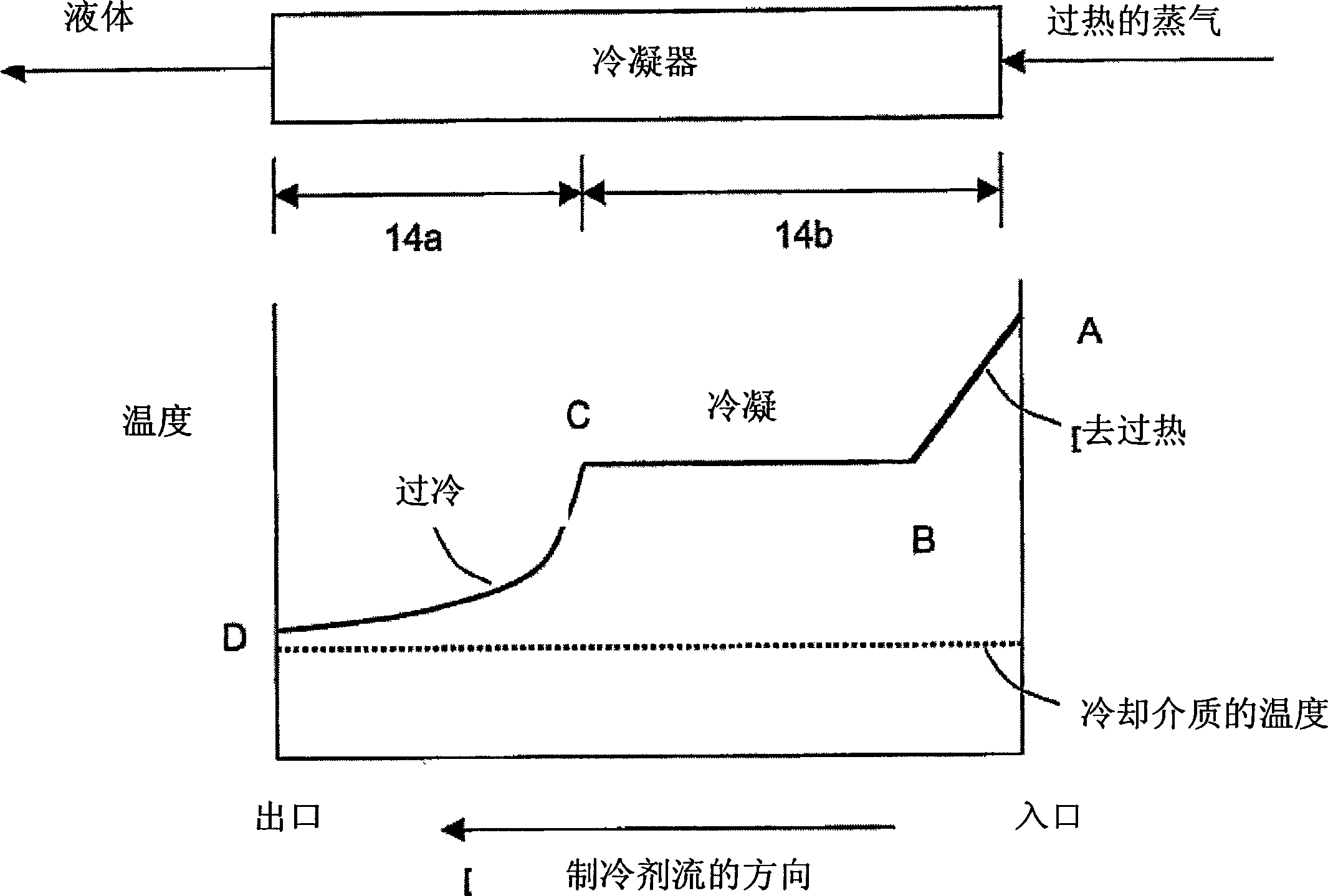
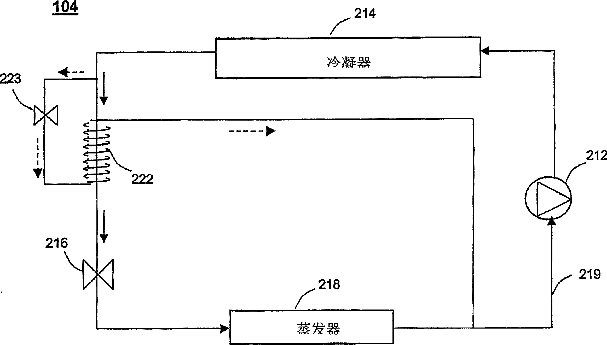
[0064] Figure 5The principle of the bypass technique is shown, where a portion of the liquid refrigerant bypasses through a bypass line or passage 27 . The refrigerant in the bypass line flows through the secondary expansion device 23, thus reducing its pressure and temperature. The cold refrigerant mixture after the secondary expansion device receives thermal energy from the hot liquid refrigerant that has left the condenser and flows through the primary refrigerant circuit while generating additional subcooling in the liquid refrigerant. The additional subcooling resulting from this bypass method makes the subcooling process in the condenser unnecessary. therefore, Figure 5 A smaller condenser 14b is shown with its subcooling section removed and indicated by a dashed rectangular box.

[0065] Figure 6 indicated that the bypass technique used larger evaporators than in an optimized system without bypass technique. Larger evaporators can be used due to the increased su...


PUM


Abstract

A refrigeration system having a primary refrigerant circuit comprising a compressor, a condenser, a primary expansion device and an evaporator connected together to form a refrigerant circuit in which A closed loop system; and a bypass line, which is connected to the outlet of the condensing device, the bypass line includes: a secondary expansion device; a heat exchange device, between the outlet of the condenser and the inlet of the primary expansion device The primary refrigerant path is thermally connected to absorb heat from the discharged refrigerant from the condenser. The condenser is reduced in size, lacking the heat transfer capacity to provide some or all of the subcooling according to conventional practice, and the heat exchanger provides some or all of the subcooling according to the capacity of the condenser. Pressure regulating means for mixing the vapors of two different pressures may also be provided to connect the outlet of the evaporator and heat exchanger with the inlet of the compressor. A method of operating a refrigeration system having a reduced volume condenser and a bypass line including a heat exchanger for providing subcooling.

Description

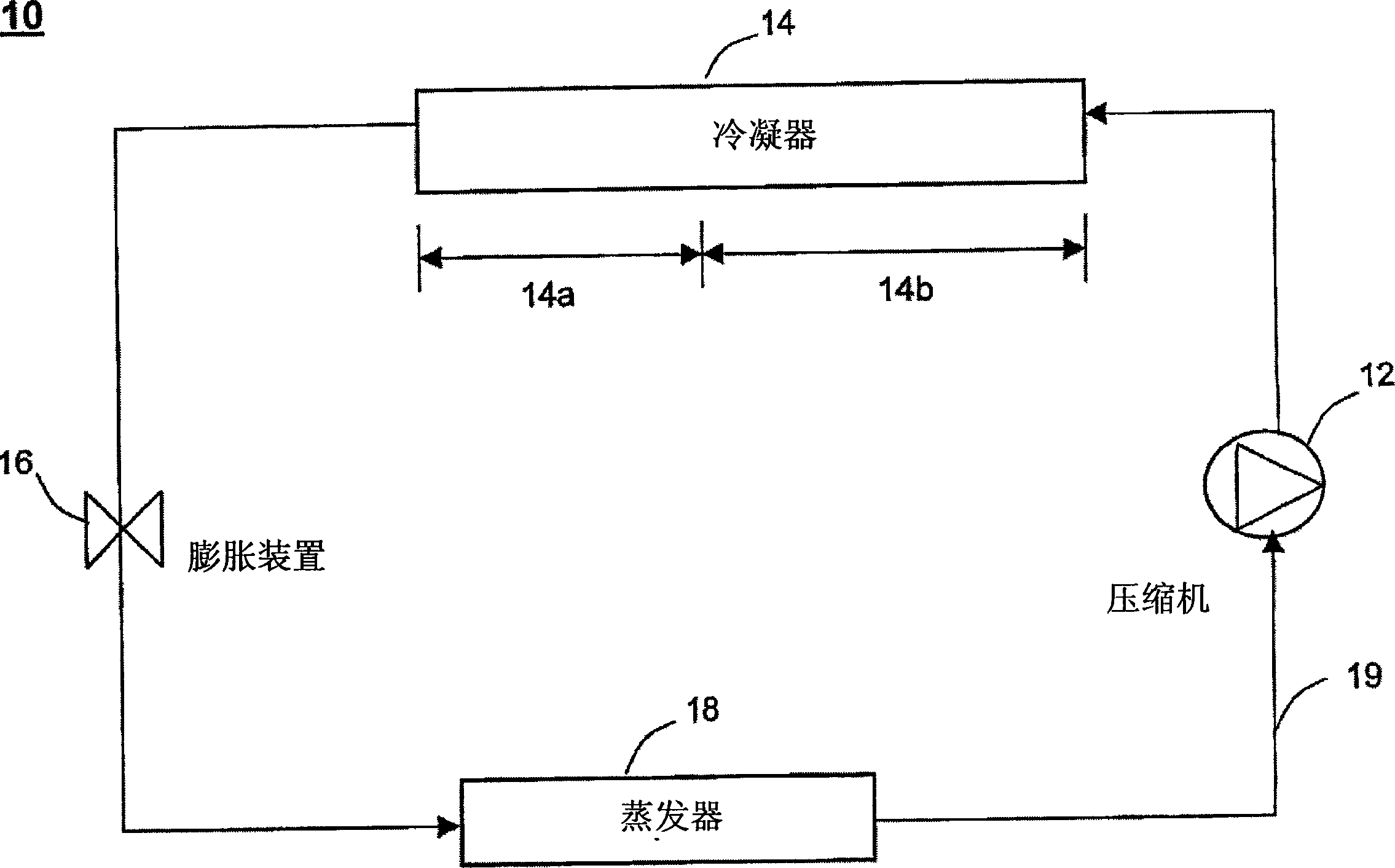
[0001] This application claims priority to US Provisional Application 60 / 426,073, filed November 11, 2002. technical field [0002] The present invention relates generally to a high efficiency refrigeration system and more particularly to a refrigeration system utilizing a subcooled bypass in combination with selection of condenser, compressor and evaporator volumes to increase overall system efficiency . Background technique [0003] figure 1 is a block diagram of a conventional refrigeration system generally indicated at 10 . The system includes a compressor 12 , a condenser 14 , an expansion device 16 and an evaporator 18 . These components are usually connected together by copper pipes (such as indicated at 19) to form a closed loop system. Refrigerants such as R-12, R-22, R-134a, R-407c, R-410a, ammonia, carbon dioxide or natural gas are circulated through the system. [0004] The main steps in the refrigeration cycle are the compression of the refrigerant by the co...

Claims


Application Information

Patent Timeline
Patent Type & Authority Applications(China)
IPC IPC(8): F25B41/00F25B5/02F25B6/04F25B9/00F25B40/00F25B43/00
CPCF25B2400/23F25B2400/13F25B40/00F25B6/04F25B5/02F25B9/006F25B2700/21151F25B43/00F25B41/00F25B2341/0011F25B2500/01
Inventor 凯奥尔浩·拜
Owner 沃特克斯·埃尔康公司
Why Eureka
Eureka Blog
Learn More