
Electromagnetic frequency filter

一种频率滤波器、电磁波的技术,应用在仪器、滤光片、光波导光导等方向,能够解决信号交调失真等问题

Inactive Publication Date: 2006-02-08
JAPAN SCI & TECH CORP +1
View PDF2 Cites 3 Cited by
  • Summary
  • Abstract
  • Description
  • Claims
  • Application Information

AI Technical Summary

Problems solved by technology

Therefore, in the structure of Patent Document 3, there is a problem that light including components other than a predetermined frequency is propagated between the two waveguides at positions other than point defects, causing cross-modulation distortion of signals.
[0010] Heretofore, an optical demultiplexer and an optical multiplexer using two-dimensional photonic crystals have been described as examples, but not only for light, but also for electromagnetic waves. In addition, in optical frequency filters (wavelength filtering) with structures other than two-dimensional photonic crystals The same problem occurs in the filter) or electromagnetic wave frequency filter

Method used


Image

  • Electromagnetic frequency filter
  • Electromagnetic frequency filter
  • Electromagnetic frequency filter

Examples


Embodiment Construction

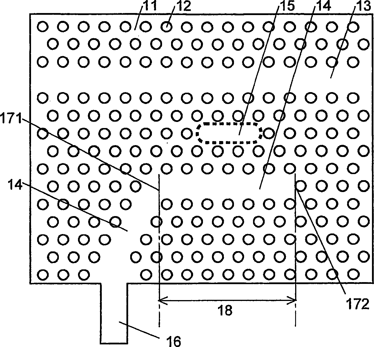
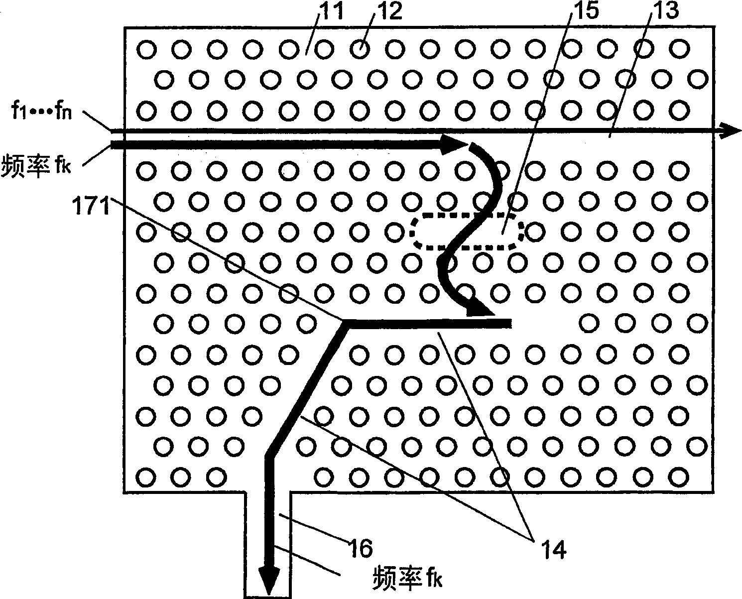
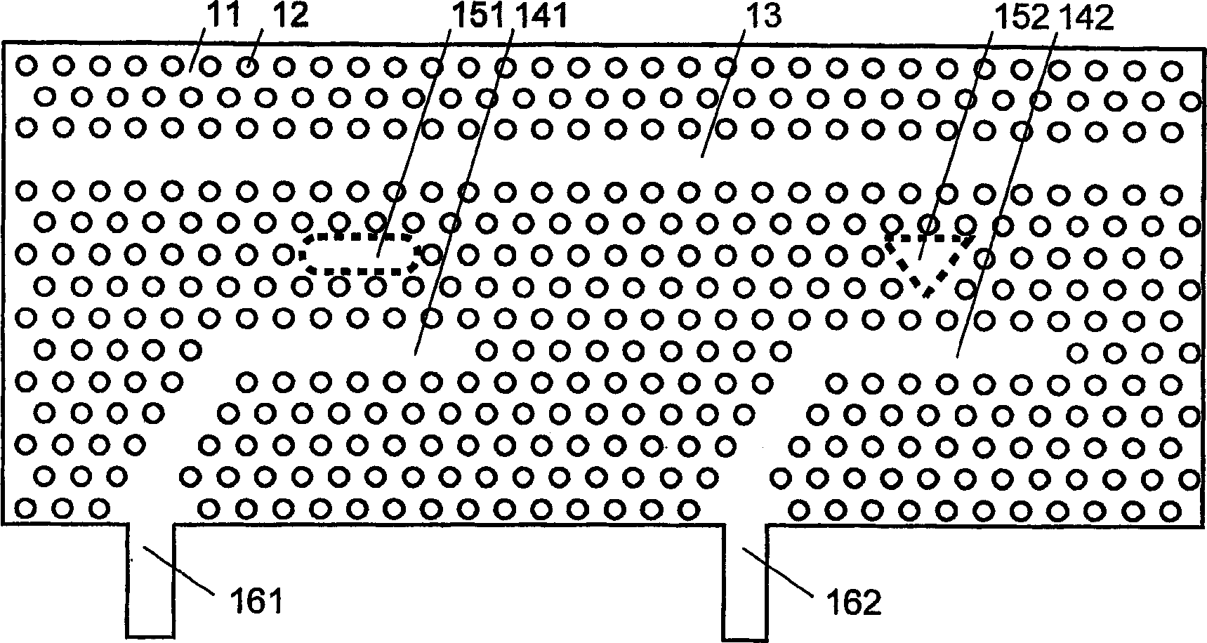
[0069] As an embodiment of the electromagnetic wave frequency filter of the present invention, in figure 1 A configuration example of an electromagnetic wave (light) frequency filter using a two-dimensional photonic crystal is shown in the figure. On the main body 11, holes 12, which are regions of different refractive indices, are periodically arranged in a triangular grating shape. The input waveguide 13 is formed by missing the hole 12 in a linear shape. Similarly, the output waveguide 14 is formed by missing the hole 12 in a linear form so that it is parallel to the input waveguide 13 within a predetermined range 18 and separated from the input waveguide 13 in a range other than the predetermined range. An external waveguide 16 is connected to one end of the output waveguide 14 . The external waveguide 16 can use, for example, a thin wire waveguide made of the same material as the main body 11 . At the other end of the output waveguide 14 , a terminal portion 172 is pro...


PUM


Abstract

An electromagnetic frequency filter comprises a resonator (15) which is arranged between and close to an input waveguide (13) and an output waveguide (14) and resonant with an electromagnetic wave of a certain frequency. The output waveguide (14) is so formed that it is parallel to the input waveguide (13) in a certain area (18) near the resonator (15) while it is at a farther distance from the input waveguide (13) in the area other than the certain area (18) when compared with the distance between the two waveguides in the certain area (18). This electromagnetic frequency filter can be preferably formed using a two-dimensional photonic crystal.

Description

technical field [0001] The present invention relates to a frequency filter for extracting light or electromagnetic waves of a predetermined frequency from a waveguide. This frequency filter is used in the field of optical communication and the like. Background technique [0002] In optical communication, in order to increase the amount of information that can be transmitted per unit time, a wavelength division multiple access (WDM) method is used in which light of multiple wavelengths (frequency) is propagated in one transmission path and different signals are carried in each light. In this wavelength division multiple access method, the light of each wavelength is mixed at the entrance side of the transmission line, and the mixed light is extracted for every wavelength at the exit side. Therefore, optical multiplexers and demultiplexers, or wavelength filters (frequency filters) are necessary. [0003] As such a wave splitter, an arrayed waveguide diffraction grating is c...

Claims


Application Information

Patent Timeline
Patent Type & Authority Applications(China)
IPC IPC(8): G02B6/12G02B5/20G02B6/122G02F1/01G02F1/313
CPCG02B6/12007B82Y20/00G02B6/1225G02B2006/12104
Inventor 野田进浅野卓高野仁路
Owner JAPAN SCI & TECH CORP
Learn More