Metal automaitic casting device and method

An automatic, metal-based technology, applied in safety devices, casting equipment, and equipment that feeds molten metal into molds, etc., can solve problems such as reduced work efficiency, reduced production efficiency, and difficulty in micro-movement

Inactive Publication Date: 2006-02-15
KG INC
View PDF0 Cites 20 Cited by
  • Summary
  • Abstract
  • Description
  • Claims
  • Application Information

AI Technical Summary

Problems solved by technology

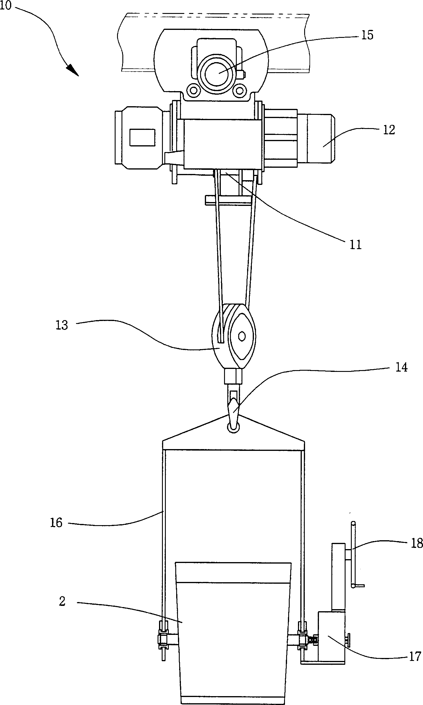
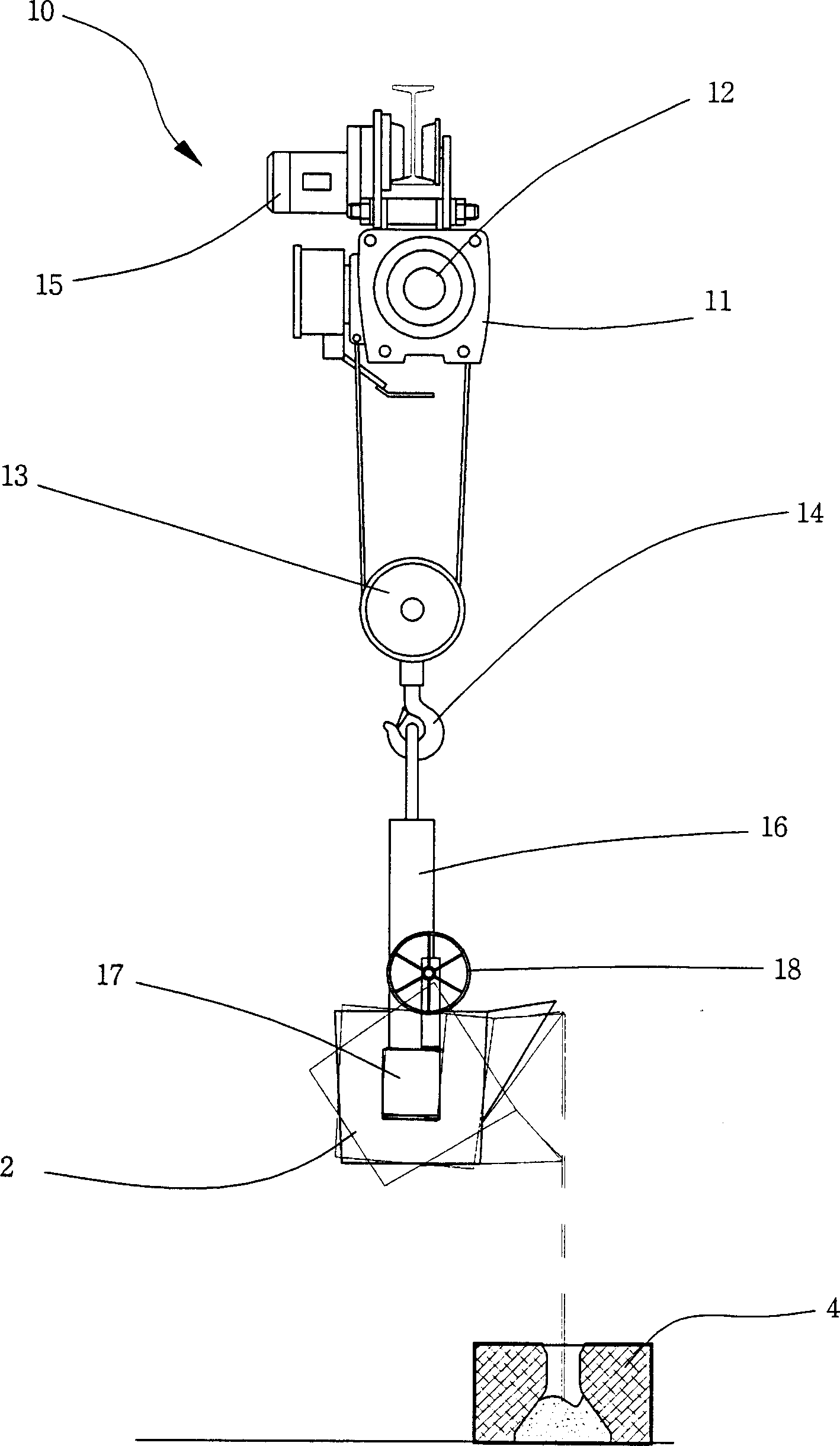
However, it is very difficult to perform precise micro-movement through mechanical operations similar to the hoisting room 10, so the staff will directly carry out the operation with the ladle 2, and there is a risk of injury, which reduces work efficiency. Spilling may cause major accidents, so there are potential safety hazards
[0017] At the same time, in the state where the ladle 2 filled with molten steel is moved up to the position of the mold 4 through the lift room 10 running horizontally, the oper

Method used


Image

  • Metal automaitic casting device and method
  • Metal automaitic casting device and method
  • Metal automaitic casting device and method

Examples


Embodiment Construction

[0064] Embodiments of the above-mentioned structure are described below with reference to the accompanying drawings.

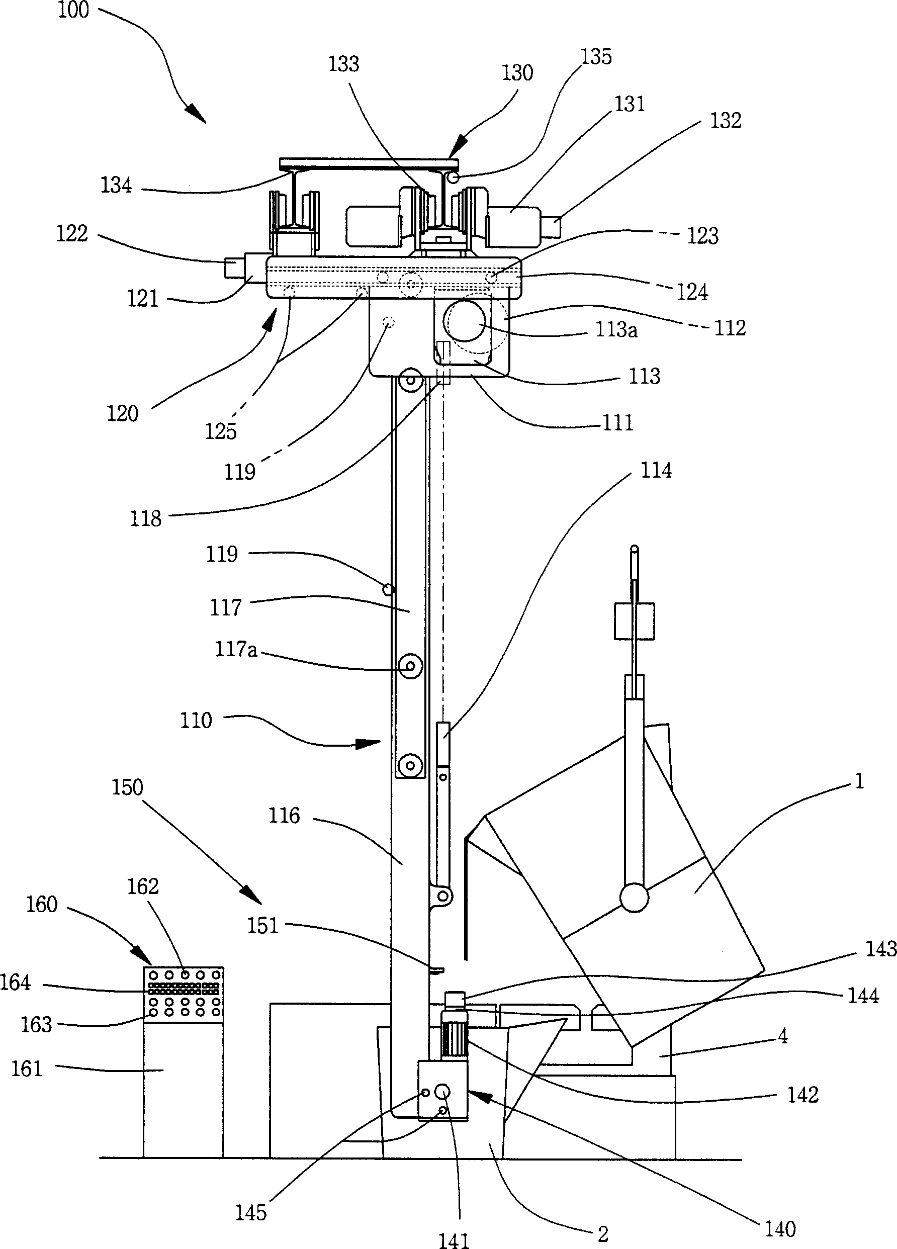
[0065] image 3 It is a schematic front view of the state of pouring molten steel into the ladle in the metal automatic casting device of the present invention, Figure 4 It is a schematic front view of the state of pouring molten steel into the mold in the metal automatic casting device of the present invention, Figure 5 It is a schematic side view of the metal automatic casting device of the present invention, Figure 6 It is a schematic flow sheet of the metal automatic casting method of the present invention, Figure 7 is a schematic flow chart of another embodiment of the metal automatic casting method of the present invention, Figure 8 is a block diagram illustrating the metal automatic casting method of the present invention, Figure 9 It is a control flowchart of the metal automatic casting method of the present invention.

[0066] Such as Fig...


PUM


Abstract

The present invention relates to a metal auto-casting arrangement, and the arrangement includes the following components: an elevator (110), a left-and-right transferring part (120), a casting ladle rotating part (140), an inducting part (150) and a control part (160). The invention also relates to a metal auto-casting method, which includes the following steps: automatic/manual choosing step (S1), a work setting step (S2), a casting ladle molten steel pouring step (S3), a casting ladle hoisting step (S4), a casting ladle transversely moving step (S5), a casting ladle right and left moving step (S6), a pouring judging step (S7), a molten steel pouring step (S8), and an operation repetition step (S9).

Description

【Technical field】 [0001] The invention relates to a metal automatic casting device and method. Specifically, molten steel molten in a furnace is poured into a ladle, and the molten steel poured into the ladle is poured into the The molten steel is automatically moved up and down, left and right, and forward and backward by using the elevator, and the molten steel is poured into the mold, and then returned to the original position, and the pouring operation is repeated to complete the casting. Use the manual operation panel installed in the control part to carry out manual operation in stages, and the control part automatically controls the molten steel, and pours according to the type of product and the position of the mold to increase the pouring speed. At the same time, because the ladle can be up and down, left and right, Back and forth transfer can produce a variety of castings on one production line, so the versatility and productivity are improved, and no matter whether ...

Claims


Application Information

Patent Timeline
IPC IPC(8): B22D37/00
CPCB22D35/04B22D37/00B22D41/00B22D46/00C22C9/04C22C21/00
Inventor 赵德来
Owner KG INC
Why Eureka
Try Eureka