Cleaning roller

A cleaning roller, cleaning technology, applied in textile and papermaking, drafting equipment, spinning machines, etc., can solve problems such as low efficiency, damage, affecting yarn evenness, knots and other quality indicators

Inactive Publication Date: 2006-02-15
DONGTAI TEXTILE MASCH CO LTD
View PDF0 Cites 1 Cited by
  • Summary
  • Abstract
  • Description
  • Claims
  • Application Information

AI Technical Summary

Problems solved by technology

[0003] Although this traditional pile roller is relatively simple and practical, it has shown obvious defects and deficiencies in practical applications: first, the existing pile roller can only remove flying flowers and floating dust on the surface of the top roller. There is nothing to do with the scale-like accumulations formed by the top rollers during the drafting and pressing process that are close to the surface of the top rollers. Once these accumulations are twisted into the yarn, they will not only directly affect the quality of the yarn such as dryness and knots indicators, and will cause yarn breakage
Especially when the temperature and humidity in the workshop are high and the static electricity on the surface of the top rollers is seriously accumulated, the scale accumulation is more difficult to remove, and the operator must manually wipe it off one by one, which is not only labor-intensive and inefficient, but also also extremely unsafe
Second, due to the long-term continuous rotation of the cashmere roller on the top roller, it is very easy to cause the surface of the cashmere roller to be delinted and damaged due to wear and tear, and lose the cleaning effect
Third, the cashmere roller not only consumes a lot of wood resources, but also is easily deformed by moisture, which directly affects the service life and even leads to scrapping

Method used


Image

  • Cleaning roller
  • Cleaning roller

Examples


Embodiment Construction

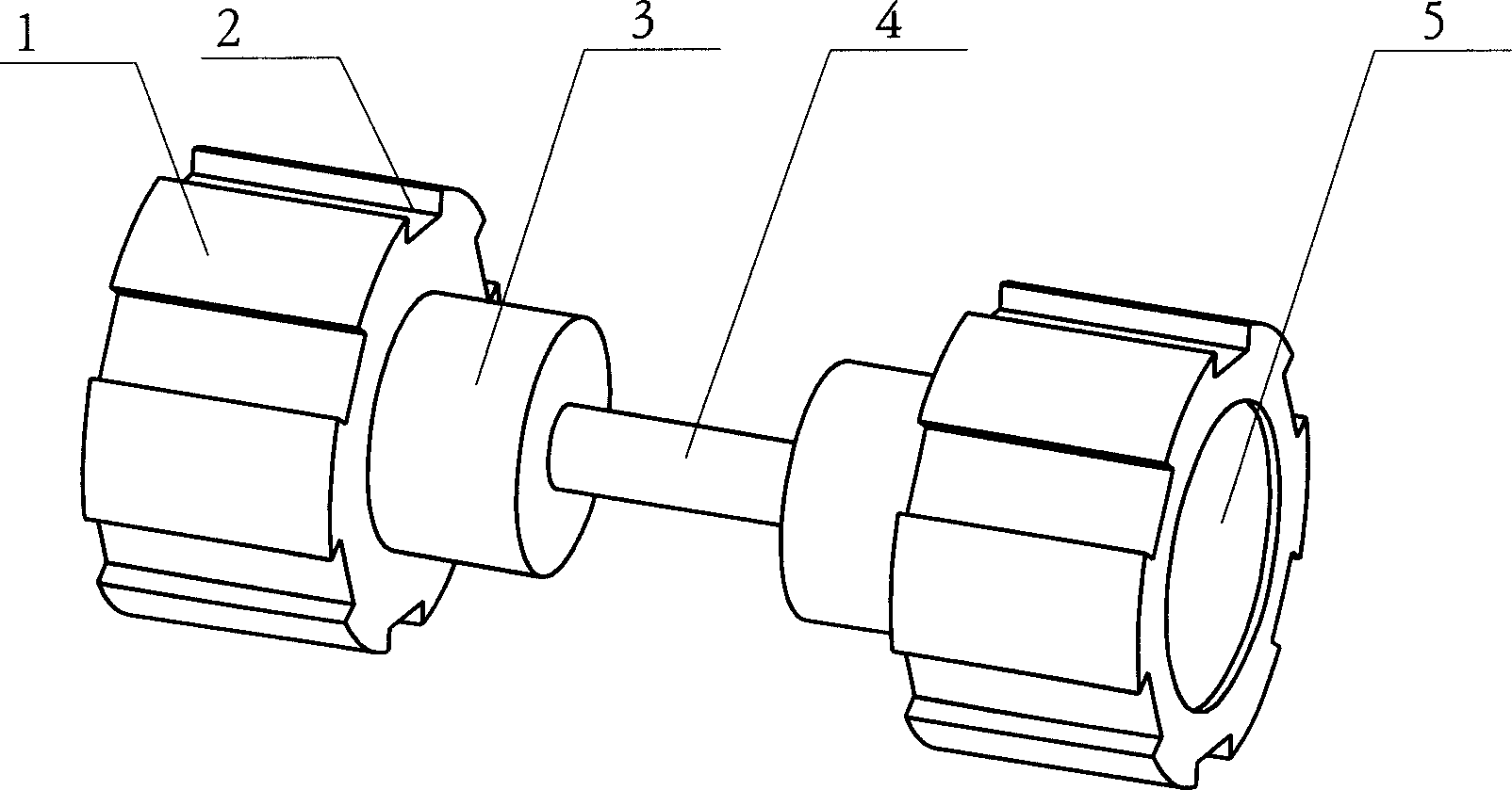
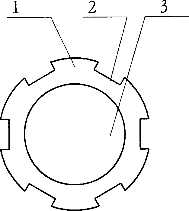
[0011] figure 1 , figure 2 The shown cleaning roller is provided with two cleaning roller bodies 1 at both ends of the mandrel 4, and the outer circumference of the cleaning roller body 1 is uniformly provided with six strip-shaped cleaning grooves 2 extending along its axial direction. An end cap 5 is installed on the outside of the cleaning roller body 1, and a cleaning roller step 3 is arranged on the inner surface of the cleaning roller body 1, and the cleaning roller steps 3 of the two cleaning roller bodies 1 face each other with a certain distance apart. The structure is beneficial to prevent axial movement of the cleaning roller body 1 after it is installed and used. When in use, the cleaning roller body 1 and the surface of the top roller rub against each other and roll. Due to the existence of the cleaning groove 2, the continuous rotation of the cleaning roller body 1 becomes uneven speed rolling, which significantly enhances the cleaning and removal of debris. I...


PUM


Abstract

This invention discloses a cleaning roller for the spinning machine, which includes cleaning roller noumenon, which has several cleaning grooves on it; the two cleaning rollers are mounted oppositely on the both extremities of the main axis. The cleaning roller uses the plastic as the material, which is applied widely in the spinning machine such as the roving machine, the spun yarn machine and so on.

Description

technical field [0001] The invention relates to a spinning machine, in particular to a roller cleaning device with a roller and a top roller drafting device in the spinning machine. Background technique [0002] In the spinning machinery that has drafting roller, top roller, the surface of top roller in the spinning machinery equipment such as roving frame, fine spinning frame is all rotatably supported with cleaning suede roller. Present cleaning fleece roller all is made up of the flocking layer of cylindrical wooden cylinder, mandrel and cylinder surface or pasting fleece layer. [0003] Although this traditional pile roller is relatively simple and practical, it has shown obvious defects and deficiencies in practical applications: first, the existing pile roller can only remove flying flowers and floating dust on the surface of the top roller. There is nothing to do with the scale-like accumulations formed by the top rollers during the drafting and pressing process that...

Claims


Application Information

Patent Timeline
Patent Type & Authority Applications(China)
IPC IPC(8): D01H5/64
Inventor 朱鹏王平
Owner DONGTAI TEXTILE MASCH CO LTD
Why Eureka
Try Eureka