Trochoid pump

A trochoid pump, pump chamber technology, applied in the direction of pumps, pump components, rotary piston type/swing piston type pump components, etc., can solve problems such as reducing pump efficiency

Inactive Publication Date: 2006-02-15
HITACHI LTD
View PDF2 Cites 7 Cited by
  • Summary
  • Abstract
  • Description
  • Claims
  • Application Information

AI Technical Summary

Problems solved by technology

This inevitably enables hydraulic fluid in the high-pressure pump chamber on the discharge side to leak into the low-pressure pump chamber on the suction side, reducing pump efficiency

Method used


Image

  • Trochoid pump
  • Trochoid pump
  • Trochoid pump

Examples


Embodiment Construction

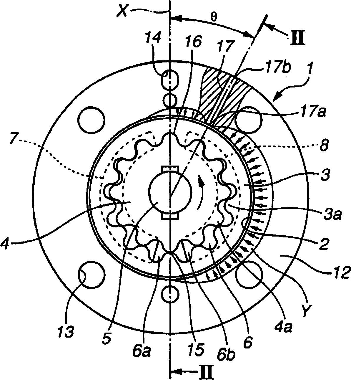
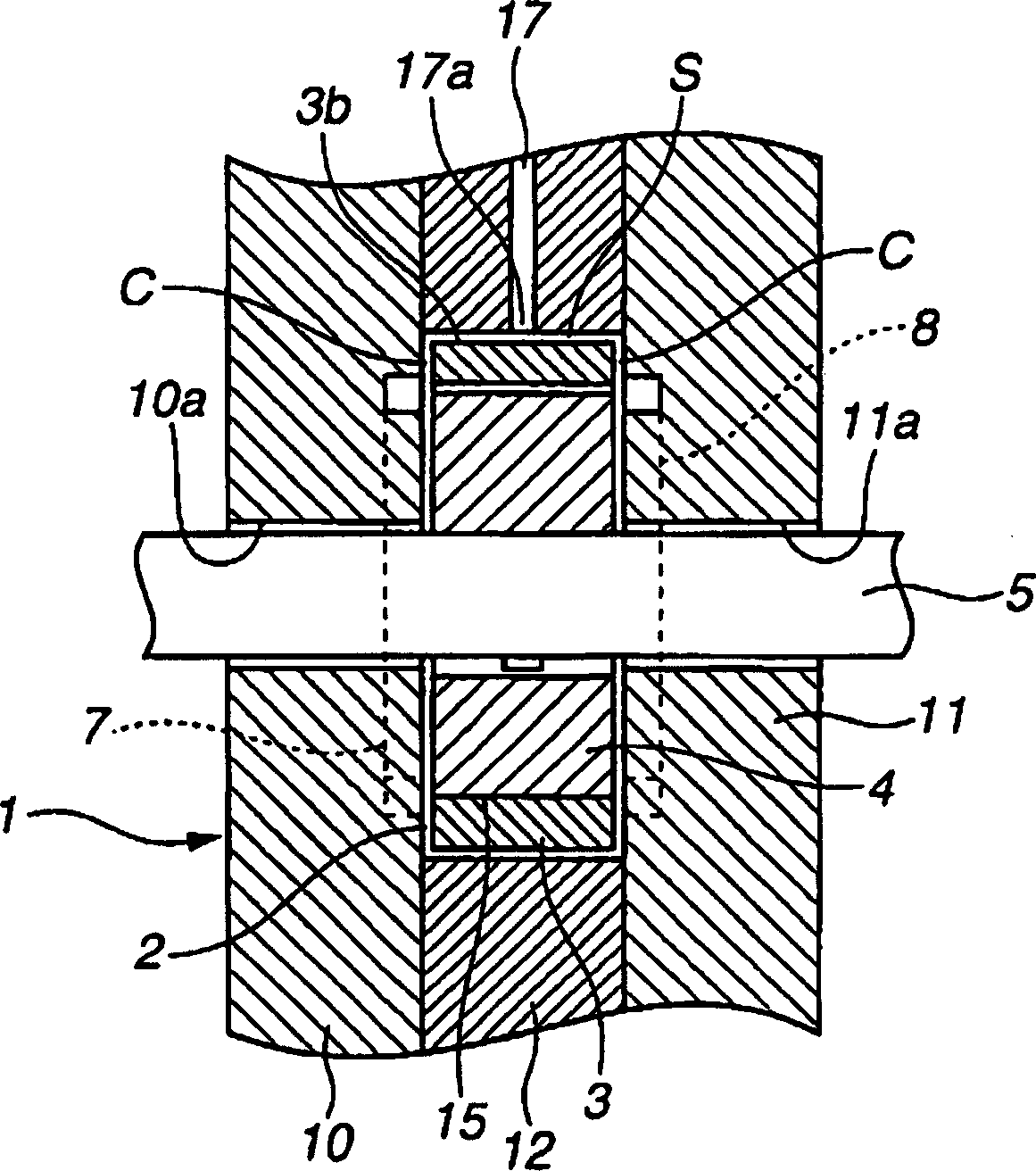
[0033] Refer below figure 1 and 2 , the figure shows the first embodiment of the trochoid pump (inscribed type gear pump) of the present invention. The trochoid pump selectively supplies hydraulic pressure to two hydraulic chambers of a hydraulic cylinder to help increase the steering force of a power steering system of a vehicle (automobile).

[0034] The trochoid pump includes a housing 1 in which is formed an annular operating chamber 2 formed on the inner peripheral side of a cam ring 12 (described later). The outer rotor 3 is rotatably fitted into the operation chamber 2, and has a plurality of internal teeth 3a continuously formed on the inner peripheral side of the outer rotor 3 in the circumferential direction. The inner rotor 4 is rotatably arranged inside the outer rotor 3 and has a plurality of outer teeth 4 a continuously formed in the circumferential direction of the inner rotor 4 . The outer teeth 4 a of the inner rotor 4 can mesh with the inner teeth 3 a of t...


PUM


Abstract

A trochoid pump for supplying hydraulic fluid to a power cylinder in a power steering system. The trochoid pump includes a housing formed therein with an annular operating chamber. Outer rotor having internal teeth and inner rotor having external teeth are rotatably accommodated in the operating chamber in such a manner that the internal and external teeth are engageable with each other. A driving shaft is provided for rotationally driving the inner rotor. A low pressure passage is opened to a clearance between an outer peripheral surface of the outer rotor and an inner peripheral surface of the operating chamber within a discharge region at side of an engaging section at which the volume of the pump chamber is the minimum so as to release a high pressure applied to the outer peripheral surface of the outer rotor, to a low pressure side.

Description

technical field [0001] The present invention relates to improvements to trochoid pumps used, for example, to supply lubricating oil to various sliding parts of automobiles, or to supply hydraulic pressure to hydraulic power cylinders to help increase steering effort in power steering systems. Background technique [0002] A trochoidal pump used, for example, in automobiles includes an outer rotor having inner teeth integrally formed on the inner peripheral side of the outer rotor. The inner rotor has outer teeth integrally formed on the outer peripheral side of the inner rotor. The outer teeth of the inner rotor are meshable with the inner teeth of the outer rotor. A plurality of pump chambers are formed between the inner teeth and the outer teeth, and include a first group of pump chambers on one side of a boundary portion at which the volume of the pump chambers is the largest and a second group of pump chambers on the other side of the boundary portion. Group pump chamb...

Claims


Application Information

Patent Timeline
Patent Type & Authority Applications(China)
IPC IPC(8): F04C15/06F04C2/10
CPCF04C2/102F04C15/0042
Inventor 仓田昌和久积巧中岫泰仁中田光昭大泷瑞生
Owner HITACHI LTD
Why Eureka
Try Eureka