Vehicular marker lamp

一种标识灯、车辆的技术,应用在车辆用标识灯领域,能够解决不能充分地均匀照射前透镜等问题,达到提高光束利用率、实现薄型化、减小深度尺寸的效果

Inactive Publication Date: 2012-05-16
KOITO MFG CO LTD
View PDF1 Cites 0 Cited by
  • Summary
  • Abstract
  • Description
  • Claims
  • Application Information

AI Technical Summary

Problems solved by technology

However, in the structure in which light from the LED is irradiated to the front lens and is reflected by the reflector, and the reflected light is irradiated to the front lens, the entire front lens cannot be illuminated uniformly enough.

Method used


Image

  • Vehicular marker lamp
  • Vehicular marker lamp
  • Vehicular marker lamp

Examples


Embodiment Construction

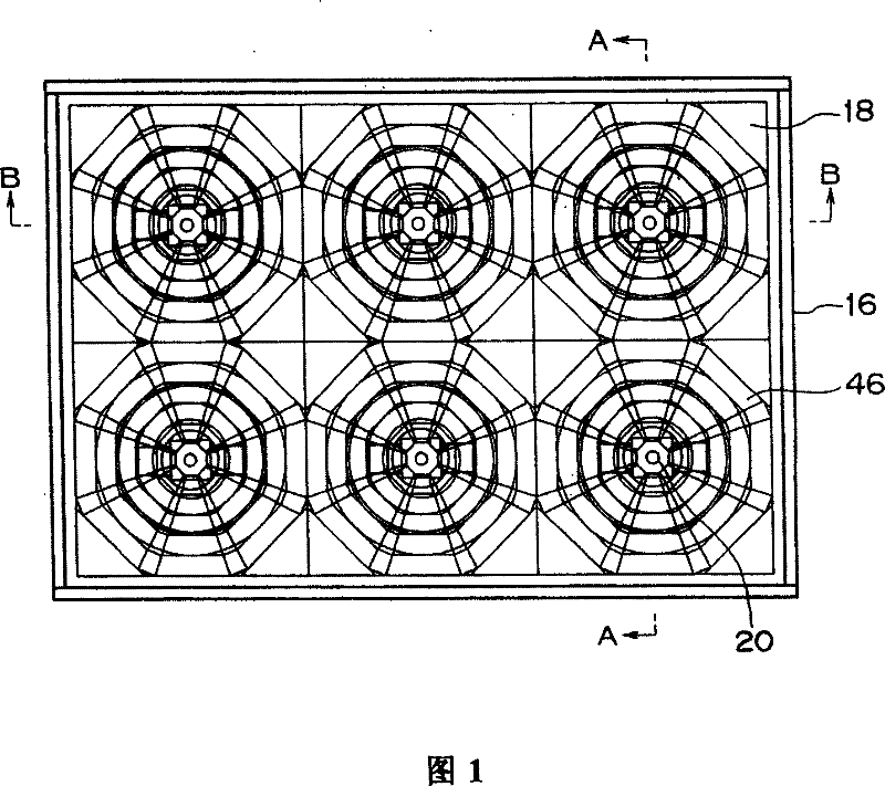
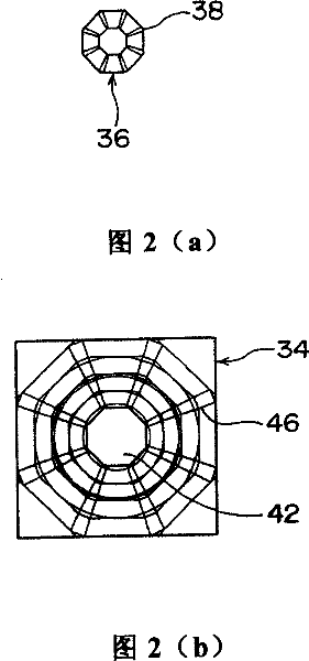
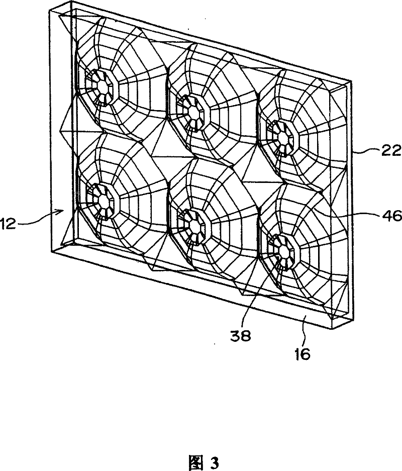
[0031] Hereinafter, embodiments of the present invention will be described based on examples. figure 1 It is a front view showing a vehicle marker lamp according to an embodiment of the present invention, and Fig. 2(a) is in figure 1 The structural diagram of the radial lens step (lens step) formed on the front side of the lens used in the shown vehicle marker lamp, FIG. 2(b) is a structural diagram of the radial lens step formed on the rear side of the same lens, image 3 yes figure 1 The oblique view of the identification lamp for the vehicle shown, Figure 4 is along figure 1 The cross-sectional view of the A-A direction, Figure 5 is along figure 1 The cross-sectional view of the B-B direction, Image 6 It is a front view showing a vehicle marker lamp according to another embodiment of the present invention, and FIG. 7(a) is in Image 6 The structural diagram of the radial lens step formed on the front side of the lens used in the shown vehicle marker lamp, FIG....


PUM


Abstract

This vehicular marker lamp is provided with: LEDs 20 each arranged with an optical axis L directed toward the front side of the lamp; a lens 12 disposed in front of the LEDs 20; and reflectors 26 disposed around the LEDs 20. On the lens 12, curved reflecting surfaces 42 each used for reflecting light from the LED 20 toward the reflector 26 to form a virtual light source image 44 of reflected light thereof at a position separated from the optical axis L, and transmission parts 34 for transmitting, to the front side of the lamp, re-reflected light in reflecting again, on reflecting surfaces 30 of the reflectors 26, the reflected light reflected on the curved reflecting surface 42 are formed; and each reflecting surface 30 is formed into a curved surface shape having a focal point at the position of the virtual light source image 44.

Description

technical field [0001] The present invention relates to a marker lamp for a vehicle, and more particularly to a marker lamp for a vehicle which uses an LED as a light source and is used as a lamp such as a tail lamp or a brake lamp. Background technique [0002] Currently, products using LEDs (Light Emitting Diodes) as light sources are known as vehicle marker lights. In this type of vehicle marker lamp, in order to increase the light-emitting area, the following structure is adopted: a reflector is arranged around the LED, and the light irradiated from the LED is directly irradiated to the front lens while being reflected by the reflector, and the reflected light Shine through the forward lens. However, in a configuration in which light from the LED is irradiated to the front lens and is reflected by the reflector, and the reflected light is irradiated to the front lens, the entire front lens cannot be sufficiently uniformly irradiated. [0003] So, if Figure 12 As shown...

Claims


Application Information

Patent Timeline
Patent Type & Authority Patents(China)
IPC IPC(8): F21S8/10F21V13/04F21Y101/02F21W101/14
CPCF21S48/215F21S48/23G02B3/0037F21S48/2212G02B3/08F21Y2101/02F21S48/24F21Y2115/10F21S43/14F21S43/26F21S43/30F21S43/40
Inventor 天野靖之夏目和典
Owner KOITO MFG CO LTD
Why Eureka
Try Eureka