Backlight source device

A backlight and light source technology, applied in optics, optical components, nonlinear optics, etc., can solve the problem of low brightness and achieve the effects of simple structure, improved beam utilization, and improved brightness

Inactive Publication Date: 2009-05-20
HONG FU JIN PRECISION IND (SHENZHEN) CO LTD +1
View PDF4 Cites 0 Cited by
  • Summary
  • Abstract
  • Description
  • Claims
  • Application Information

AI Technical Summary

Problems solved by technology

[0007] In order to overcome the defect of low luminance of the prior art backlight device, the present invention provides a backlight device with high luminance and simple structure

Method used


Image

  • Backlight source device
  • Backlight source device
  • Backlight source device

Examples


Embodiment Construction

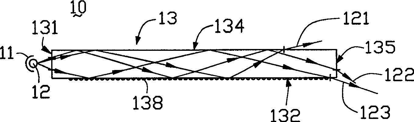
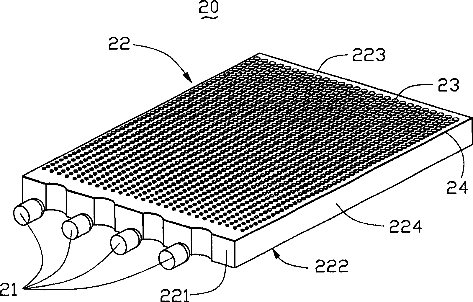
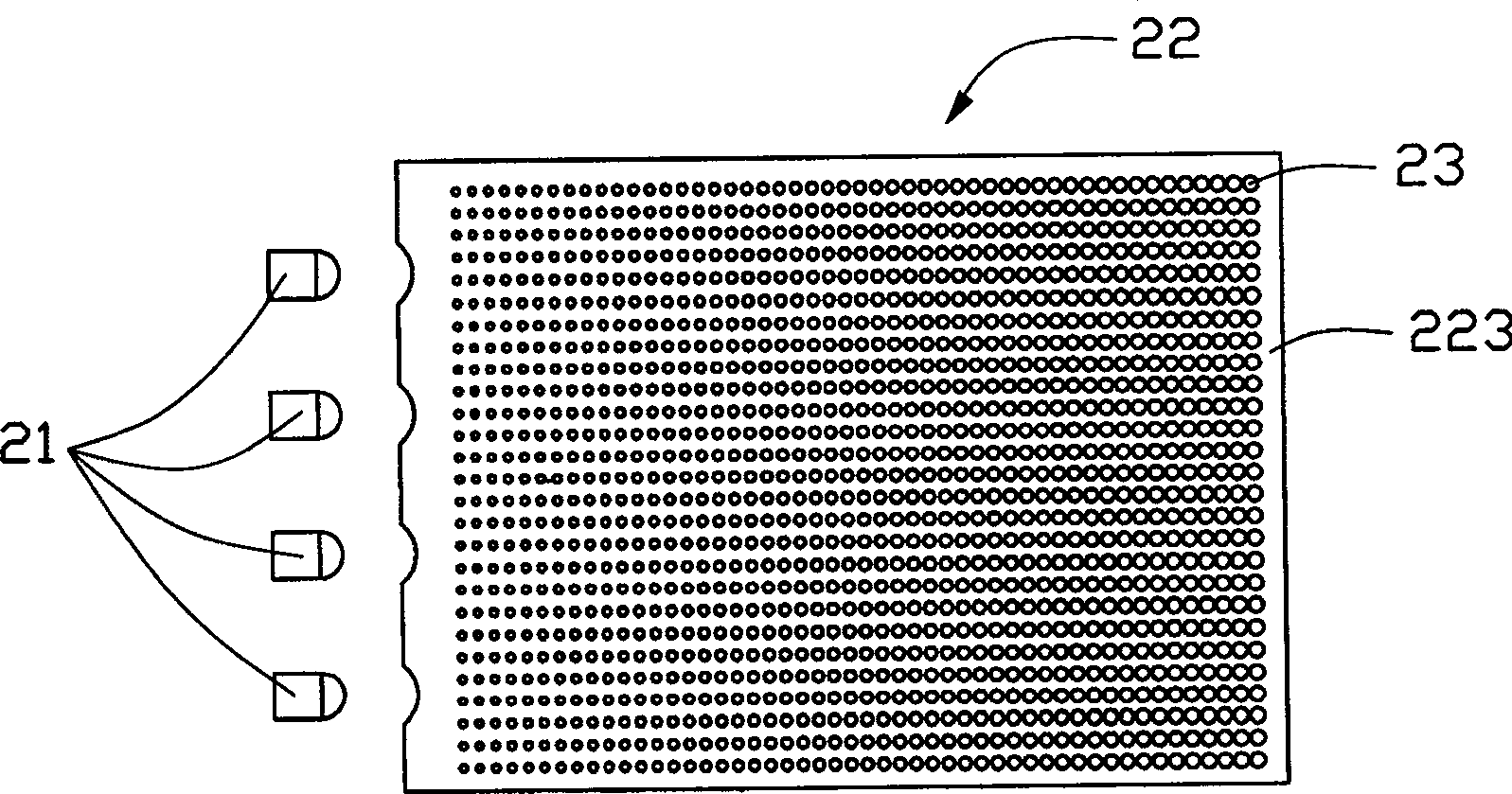
[0023] see figure 2 The backlight device 20 of the present invention includes a plurality of point light sources 21 and a light guide plate 22. The light guide plate 22 guides the transmission direction of the light beams emitted from the point light sources 21 and converts them into surface light sources for emission.

[0024] The point light source 21 can be a light emitting diode or a small light bulb. Moreover, the required color and brightness of the light source can be adjusted by disposing a plurality of light emitting diodes or small light bulbs of different colors.

[0025] The light guide plate 22 is flat and made of transparent materials such as acrylic, glass or polycarbonate. Including a light incident surface 221, a light exit surface 222 intersecting the light incident surface 221, a bottom surface 223 and a plurality of side surfaces 224 opposite to the light exit surface 222, the bottom surface 223 has a plurality of scattering units 23, and the bottom surfa...


PUM


Abstract

This invention discloses a negative light source apparatus which comprises light source and light conducting plate which is composed of at least one light incidence surface, light outgoing surface vertical to the incidence surface and the base surface of the outgoing surface with several scattering units in and with a luminescent coating formed by luminescent materials on. The light source is located against the incidence surface. This apparatus in this invention is of high out going light brilliance and is of simple structure.

Description

【Technical field】 [0001] The invention relates to a backlight source device, in particular to a side-light type backlight source device with high luminance. 【Background technique】 [0002] Due to the advantages of lightness, thinness, and low power consumption, liquid crystal displays are widely used in modern information equipment such as notebook computers, mobile phones, and personal digital assistants. Because the liquid crystal itself in the liquid crystal display does not have light-emitting properties, it is necessary to provide a backlight device for it to realize the display function. [0003] As we all know, the backlight device needs to have higher luminance and uniformity of light output to meet the predetermined requirements, so as to improve the color contrast of the liquid crystal display, the brightness effect of the full screen area and the viewing angle of the whole machine. In addition, in order to meet the light and thin requirements of the liquid crysta...

Claims


Application Information

Patent Timeline
Patent Type & Authority Patents(China)
IPC IPC(8): G02F1/13357G02B5/02G02B1/10G02F1/1335
Inventor 吕昌岳余泰成陈杰良
Owner HONG FU JIN PRECISION IND (SHENZHEN) CO LTD
Why Eureka
Try Eureka