Vehicle Lamps

A technology for lamps and vehicles, which is applied in the direction of headlights, vehicle components, lighting and heating equipment, etc. It can solve the problems of reduced brightness of light distribution patterns and can not be obtained, and achieve the effect of improving the utilization rate of light beams

Active Publication Date: 2021-01-29
KOITO MFG CO LTD
View PDF28 Cites 0 Cited by
  • Summary
  • Abstract
  • Description
  • Claims
  • Application Information

AI Technical Summary

Problems solved by technology

[0007] That is, a projection-type vehicle lighting device configured to reflect light from a luminous body emitted by laser irradiation by a reflector is suitable for forming a bright spot-like light distribution pattern (for example, for enhancing a high-beam light distribution pattern). The light distribution pattern of the central luminosity), but if an opening as described in the above-mentioned "Patent Document 1" is formed in the reflector, no reflected light can be obtained from the formation area of ​​the opening, so the corresponding light distribution pattern Reduced brightness

Method used


Image

  • Vehicle Lamps
  • Vehicle Lamps
  • Vehicle Lamps

Examples


Embodiment Construction

[0078] Hereinafter, embodiments of the present invention will be described using the drawings.

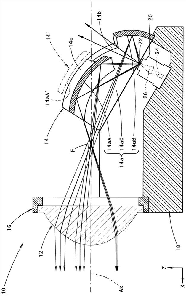
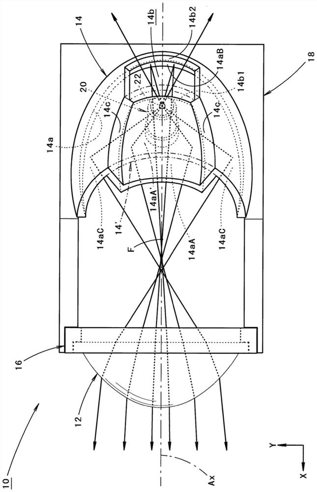
[0079] figure 1 is a side sectional view showing a vehicle lamp 10 according to an embodiment of the present invention, figure 2 is its top view.

[0080] In these figures, the direction indicated by X is "front" as a lamp ("front" as a vehicle), the direction indicated by Y is "rightward", and the direction indicated by Z is "upward". The same applies to figures other than these figures.

[0081] As shown in these figures, the vehicle lamp 10 according to the present embodiment is configured as a projection type lamp unit used in an assembled state as a part of a headlight.

[0082] That is, the vehicular lamp 10 is configured to include: a projection lens 12; a luminous body 22 as a light source disposed on the rear side of the rear focal point F of the projection lens 12; The light emitted from the body 22 is reflected toward the projection lens 12 .

[0083] The projectio...


PUM


Abstract

In a projector-type vehicle lighting device configured to reflect light from a luminous body that emits light by laser irradiation on a reflector, a bright light distribution pattern can be formed even when the reflector has an opening. As the reflection mirror, an opening is formed at a portion located on an extension line of the optical path of the laser light from the laser light emitting element to the light emitter. In addition, the reflective surface of the reflector is formed in a state where the first reflective region located on the front side of the opening is displaced toward the illuminant 22 side with respect to the second reflective region located on the rear side of the opening. Thus, compared with the case where the first reflection region is formed as a curved surface shape in which the second reflection region is extended as it is in the prior art, the solid angle based on the light emission center of the luminous body is ensured to be large, and the response to the light emission is improved. The beam utilization of the outgoing light from the illuminant.

Description

technical field [0001] The present invention relates to a projection type vehicle lamp having a reflector. Background technique [0002] Conventionally, there is known a projection-type vehicle lighting device configured to allow light from a light source reflected by a reflector to enter a projection lens, and it is also known to use a luminous body that emits light when irradiated with laser light from a laser light-emitting element as the light source. . [0003] In "Patent Document 1", as the reflector of the vehicle lamp described above, it is described that a reflector penetrating through the reflector is formed at a position located on the extension line of the optical path of the laser light from the laser light emitting element to the light emitter. opening. [0004] Patent Document 1: Japanese Patent Laid-Open No. 2015-146396 [0005] Like the vehicular lamp described in the above-mentioned "Patent Document 1", if an opening is formed in the reflector at a posit...

Claims


Application Information

Patent Timeline
Patent Type & Authority Patents(China)
IPC IPC(8): F21S41/16F21V5/04F21V7/04F21W102/13
CPCF21V5/04F21V7/04F21S41/16F21W2102/13F21S41/176F21S41/255F21S41/333F21S45/70B60Q1/04F21V7/09F21V13/04F21S41/295F21S41/33
Inventor 松本昭则
Owner KOITO MFG CO LTD
Why Eureka
Try Eureka