Impedance conversion circuit, drive circuit, and control method therefor

An impedance transformation circuit and voltage technology, which is applied in the control field of impedance transformation circuits, driving circuits and impedance transformation circuits, can solve the problems of increased design area and high cost, and achieve the effect of reducing proportion, cost reduction and simple structure.

Inactive Publication Date: 2006-02-15
SEIKO EPSON CORP
View PDF1 Cites 2 Cited by
  • Summary
  • Abstract
  • Description
  • Claims
  • Application Information

AI Technical Summary

Problems solved by technology

Therefore, with the multi-gray scale, the proportion of the wiring area of ​​the gray scale voltage signal line group is increasing, and the increase in the design area leads to high cost.

Method used


Image

  • Impedance conversion circuit, drive circuit, and control method therefor
  • Impedance conversion circuit, drive circuit, and control method therefor
  • Impedance conversion circuit, drive circuit, and control method therefor

Examples


Embodiment Construction

[0058] Hereinafter, preferred embodiments of the present invention will be described with reference to the drawings. The embodiments described below do not unduly limit the content of the invention described within the scope of the claims. In addition, not all of the configurations described below are necessarily essential configuration requirements of the present invention.

[0059] 1. Liquid crystal device

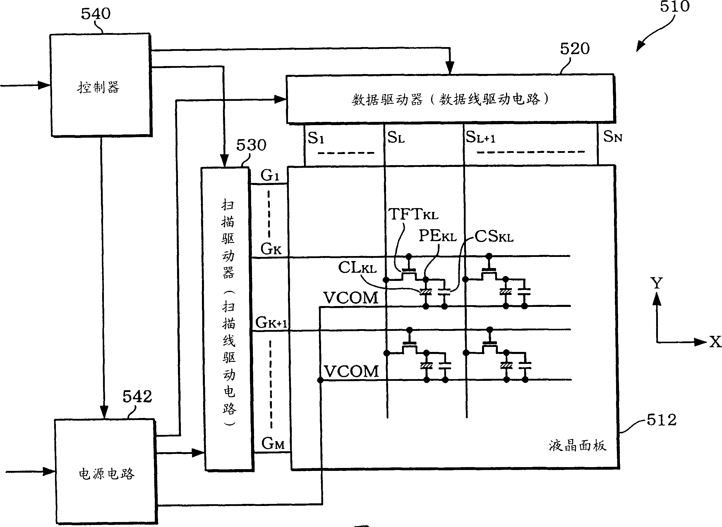
[0060] figure 1 A block diagram of a liquid crystal device to which the impedance conversion circuit of this embodiment is applied is shown.

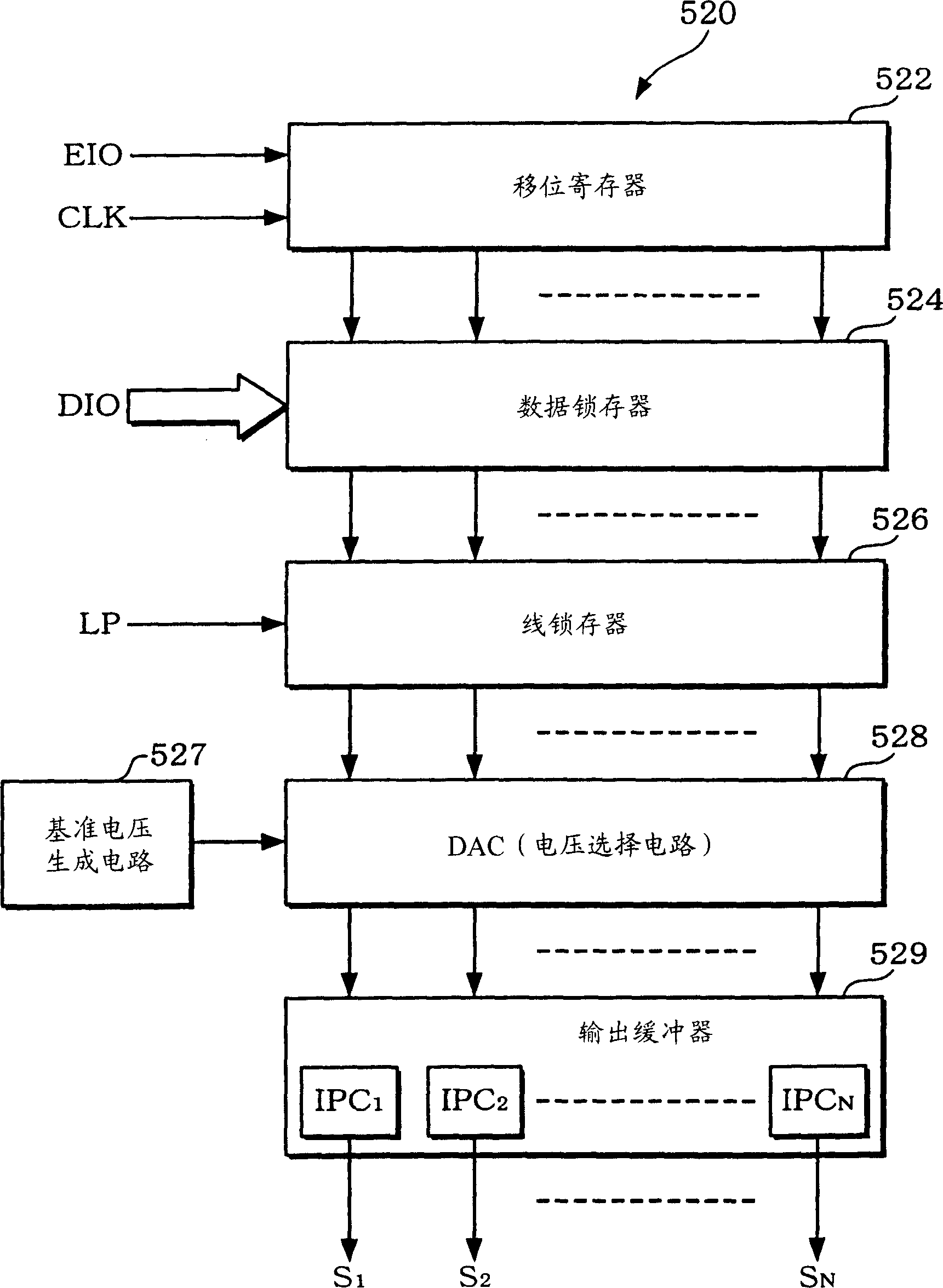
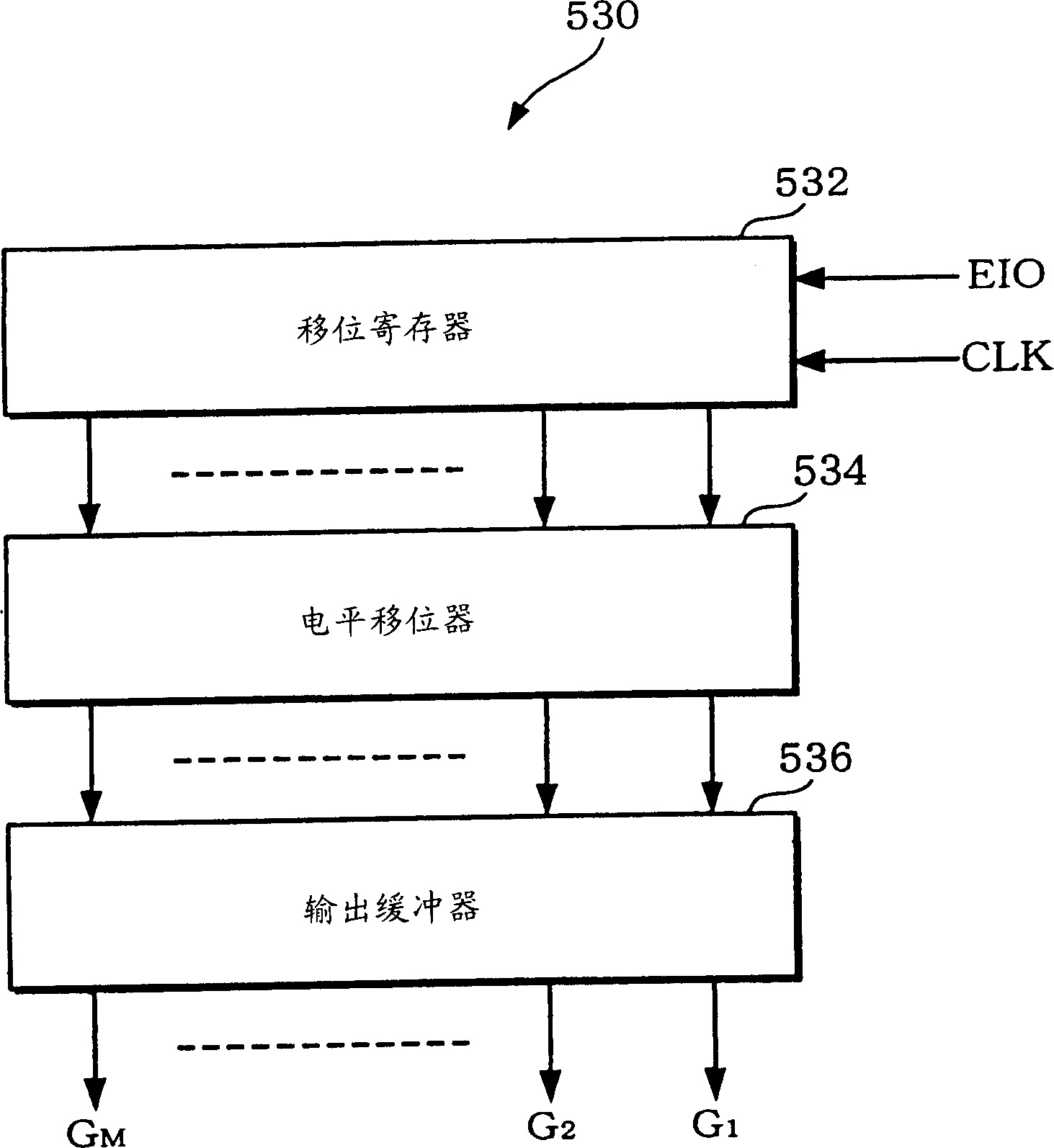
[0061] The liquid crystal device (display device in a broad sense) 510 includes a liquid crystal panel (display panel in a broad sense) 512, a data driver (data line drive circuit) 520, a scan driver (scan line drive circuit) 530, a controller 540, and a power supply circuit. 542. The liquid crystal device 510 does not necessarily include all of these circuit blocks, and some of them may be omitted.

[0062] Here, the liquid...


PUM


Abstract

An impedance conversion circuit for outputting a voltage corresponding to (j+K) (j, k: positive integers) bits of gray scale data, including: an input for receiving an input voltage selected from 2 levels of voltages in accordance with high j bit(s) of the gray scale data; and an output for outputting an output voltage corresponding to low k bit(s) of the gray scale data from 2 levels of voltages obtained by changing a potential of the input voltage.

Description

technical field [0001] The invention relates to an impedance transformation circuit, a drive circuit and a control method for the impedance transformation circuit. Background technique [0002] As we all know, as liquid crystal panels (electro-optical devices in a broad sense) used in electronic devices such as mobile phones, there are simple matrix liquid crystal panels, thin film transistors (ThinFilm Transistor: hereinafter, referred to as TFT) and other active matrix devices using switching elements. LCD panel. [0003] Compared with the active matrix method, the simple matrix method is easier to achieve lower power consumption, but it is difficult to realize multi-color and animation display. On the other hand, the active matrix method facilitates multi-color and animation display, but it is difficult to achieve low power consumption. [0004] In recent years, in portable electronic devices such as mobile phones, in order to provide high-quality images, there is an in...

Claims


Application Information

Patent Timeline
Patent Type & Authority Applications(China)
IPC IPC(8): G09G3/36G09G3/20G02F1/133
CPCG09G2310/027G09G3/3688G09G3/36H03F3/45G09G3/20
Inventor 牧克彦
Owner SEIKO EPSON CORP
Why Eureka
Try Eureka