
Signal clock demodulating device

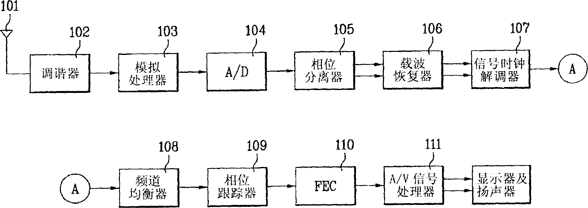
A demodulation device and signal technology, which is applied in the direction of image communication, TV, color TV parts, etc., can solve the problem of unable to normally perform signal clock demodulation processing, etc., and achieve the effect of improving jitter characteristics and performance

Inactive Publication Date: 2006-02-15
LEJIN GUANGDIAN ELECTRONIC CO LTD SHANGHAI
View PDF0 Cites 0 Cited by
  • Summary
  • Abstract
  • Description
  • Claims
  • Application Information

AI Technical Summary

Problems solved by technology

That is, when there is noise (ghosting) caused by multiple paths in the transmission channel, the frequency band signal required for signal clock demodulation becomes very small, so it is greatly affected by the surrounding frequency data, and cannot Normal signal clock demodulation processing

Method used


Image

  • Signal clock demodulating device
  • Signal clock demodulating device
  • Signal clock demodulating device

Examples


Embodiment Construction

[0052] The other purposes, features and effects of the embodiments of the present invention will be described in detail with reference to the pictures, so as to have a further clear understanding of the present invention.

[0053] Referring to the pictures, the structure and function of the embodiment of the present invention are described in detail as follows. The structure and function shown and illustrated in the description are only an illustration of an embodiment of the present invention, and the technical idea and core structure and function of the present invention are not It is not limited to several specific examples described below.

[0054] Figure 7 It is a structural block diagram of an embodiment of the signal clock demodulation device 700 developed according to the present invention. Here, the signal clock demodulation device developed according to the present invention is composed of the following structure: that is, the baseband digital signal output from th...


PUM


Abstract

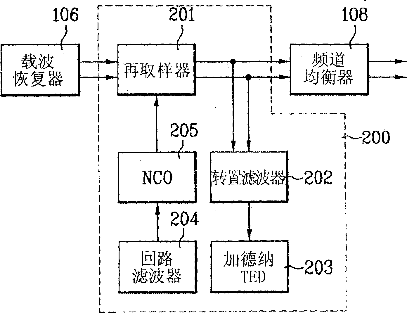
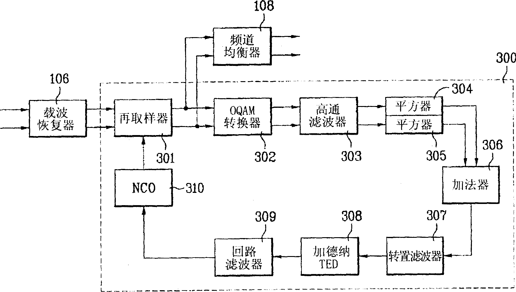
The invention relates to signal clock demodulating device for digital TV receiver. Wherein, using time error detector with nonlinear unit to detect the time error for demodulating signal clock; the front end of the said detector is arranged with an OQAM converter, a high-pass filter, a squarer and an adder. It can eliminate the unnecessary compositions and improves jitter performance. This invention can also use gain regulator and DC calculator to adjust the tone for signal clock and improve demodulating device performance on the disturbance from multi-way.

Description

technical field [0001] The present invention relates to the technology of the digital television receiver, especially the technology of the signal clock demodulation device recovering the signal clock from the received data through the non-linear algorithm. Background technique [0002] At present, in most digital transmission systems and the ATSC (Advanced Television Systems Committee) and 8 VSB (Vestigial SideBand) transmission systems of the American digital TV transmission method, in order to improve the frequency efficiency, only the uploaded data is sent out in the transmission signal. That is, information about the relevant clocks required by the receiver to recover the data is not uploaded in the transmitted signal. Therefore, the receiving side needs to generate the same clock as that used in the transmission signal in order to restore the received signal in which only data exists, and the part that performs this function is the signal clock demodulator. [0003] ...

Claims


Application Information

Patent Timeline
Patent Type & Authority Applications(China)
IPC IPC(8): H04N5/44H04N5/455
Inventor 金悳
Owner LEJIN GUANGDIAN ELECTRONIC CO LTD SHANGHAI
Learn More