
Video transmission system, video transmission device, video reception device, and video transmission method

A video receiving and video technology, applied in the direction of digital video signal modification, selective content distribution, pulse modulation TV signal transmission, etc., can solve the problem of low image quality, motion smoothness, error recovery ability, spatial resolution processing complexity, Problems such as different terminal quality

Inactive Publication Date: 2006-02-15
PANASONIC CORP
View PDF1 Cites 11 Cited by
  • Summary
  • Abstract
  • Description
  • Claims
  • Application Information

AI Technical Summary

Problems solved by technology

[0005] However, when a plurality of terminals receive video at the same time, since the capability of the terminal receiving the video and the characteristics (reception area) of the network used by each terminal are different, there is a problem that each terminal is considered necessary different quality
[0009] However, with the above-mentioned conventional technology, although it is possible to receive video whose image quality coincides with the transmission bit rate, a plurality of terminals cannot individually freely select the type of quality to be given priority (for example, image quality as described above, motion smoothness, error resilience, spatial resolution, or processing complexity)
[0010] For example, within a limited transmission bit rate, a terminal with a large display screen is better off receiving a video with high image quality in which priority is given to consecutive images, rather than a video with smooth motion but low image quality, even if the motion is not smooth

Method used


Image

  • Video transmission system, video transmission device, video reception device, and video transmission method
  • Video transmission system, video transmission device, video reception device, and video transmission method
  • Video transmission system, video transmission device, video reception device, and video transmission method

Examples


Embodiment 1

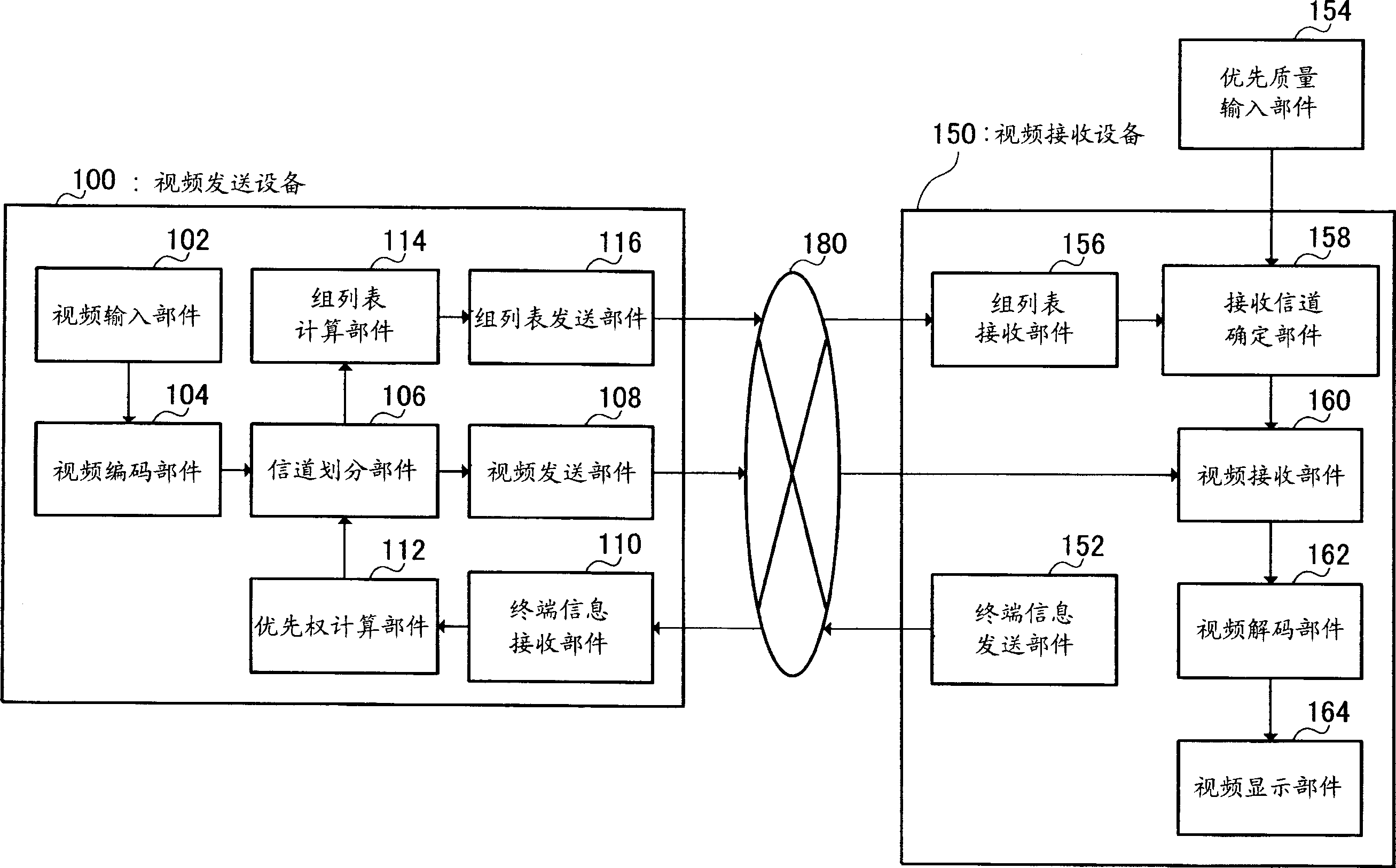
[0047] In this embodiment, a video transmission device is described whereby, by performing channel division of hierarchically encoded data using quality and bit rate, and transmitting data on an independent channel after adding priority calculated using terminal information, And also transmitting a group list in which channels are grouped by quality, a receiving terminal can select a quality to be given priority, and can receive a video with a quality suitable for terminal characteristics according to network conditions.

[0048] figure 2 is a diagram showing the configuration of a video distribution system according to Embodiment 1 of the present invention.

[0049] This video transmission system has a video transmission device (hereinafter referred to as "transmission terminal") 100 for transmitting video, a video reception device (hereinafter also referred to as "reception terminal") 150 for receiving video, and a video to be transmitted from video transmission device 100....

Embodiment 2

[0120] In this embodiment, a video transmission system is described whereby channel division of hierarchically coded data is performed by utilizing quality and bit rate, and on separate channels after adding priority calculated using input video information Sending data, and also sending a group list classified by quality, a receiving terminal can select a quality to be given priority, and can receive a video having a quality consistent with network conditions and suitable for terminal characteristics.

[0121] Figure 13 is a diagram showing the configuration of a video distribution system according to Embodiment 2 of the present invention. The video sending device 200 and the video receiving device 250 in this video sending system have and respectively in figure 2 Basic structures similar to those of the video transmitting device 100 and the video receiving device 150 in the video transmitting system shown in figure 2 The same code in , and its description is omitted.

...

Embodiment 3

[0142] In this embodiment, a video transmission system is described whereby, by dividing hierarchically coded data using quality and bit rate, and adding priority calculated on a packet-by-packet basis in each channel independently and also transmits a group list classified by quality, the receiving terminal can select the quality to be given priority, and can receive the quality video.

[0143] Figure 15 is a diagram showing the configuration of a video distribution system according to Embodiment 3 of the present invention. The video sending device 300 in this video sending system has the same figure 2 The basic structure of the video transmission device 100 in the video transmission system shown in figure 2 The same code in , and its description is omitted. In addition, the video receiving device 150 is connected with figure 2 are identical to those shown in , so their descriptions are omitted.

[0144] The feature of this embodiment is that, while in Embodiment 1 ...


PUM


Abstract

There are provided a video transmission system, a video transmission device, a video reception device, and a video transmission method in which each terminal can receive video of quality appropriate for the terminal when video is received simultaneously by a plurality of terminals having different characteristics. In the system, a transmission terminal (100) performs channel division of hierarchically encoded data according to its quality and band in a channel division section (106), adds to the data, the priority calculated in a priority calculation section (112) by using terminal information, and transmits the data from a video transmission section (108) via a separate channel. Moreover, a group list calculation section (114) calculates a group list in which channels are grouped according to the quality and transmits it from a group list transmission section (116). On the other hand, a reception terminal (150) decides the reception channel in a reception channel decision section (158) by using the priority quality and the group list which have been input and receives the video in a video reception section (160).

Description

technical field [0001] The invention relates to a video sending system for sending video through a network. Background technique [0002] Video data transmitted by a conventional video transmission system is generally compressed-encoded to a fixed bit rate or below by a method such as H.261 or MPEG (Motion Picture Experts Group), so that the video data can be transmitted at a fixed transmission bit rate, and Once the video data has been encoded, the video quality cannot be changed even if the transmission bit rate is changed. [0003] However, with the diversification of networks in recent years, transmission path bit rate fluctuations have increased, and video data capable of performing video transmission of quality equivalent to multiple bit rates has become necessary. In response to this need, a layered encoding method that has a layered structure and can handle multiple bit rates has been standardized. Among such layered encoding methods, specifically, recently standar...

Claims


Application Information

Patent Timeline
Patent Type & Authority Applications(China)
IPC IPC(8): H04N7/24H03M7/30H04N19/102H04N19/00H04N19/134H04N19/136H04N19/14H04N19/157H04N19/169H04N19/189H04N19/30H04N19/37H04N19/44H04N21/2343H04N21/258H04N21/2662H04N21/658
CPCH04N21/6582H04N21/25808H04N21/234327H04N21/2662
Inventor 本田义雅上野山努
Owner PANASONIC CORP
Learn More