Toilet tank attachment bracket with unitary spring arm

A spring arm, water tank technology, used in flushing equipment with water tanks, flushing toilets, water supply devices, etc.

Active Publication Date: 2006-02-22
KOHLER CO
View PDF2 Cites 2 Cited by
  • Summary
  • Abstract
  • Description
  • Claims
  • Application Information

AI Technical Summary

Problems solved by technology

However, this requires additional components

Method used


Image

  • Toilet tank attachment bracket with unitary spring arm
  • Toilet tank attachment bracket with unitary spring arm
  • Toilet tank attachment bracket with unitary spring arm

Examples


Embodiment Construction

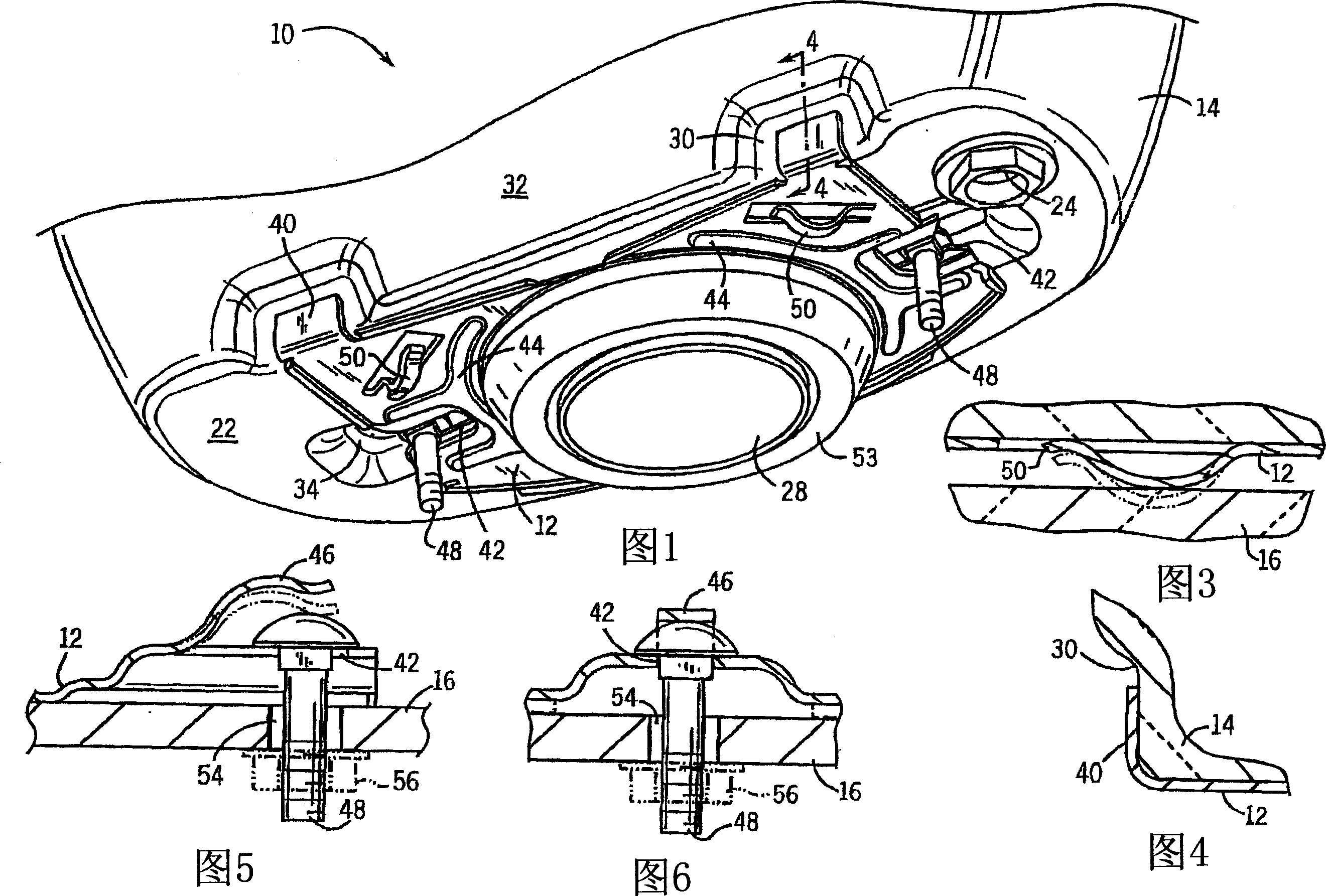
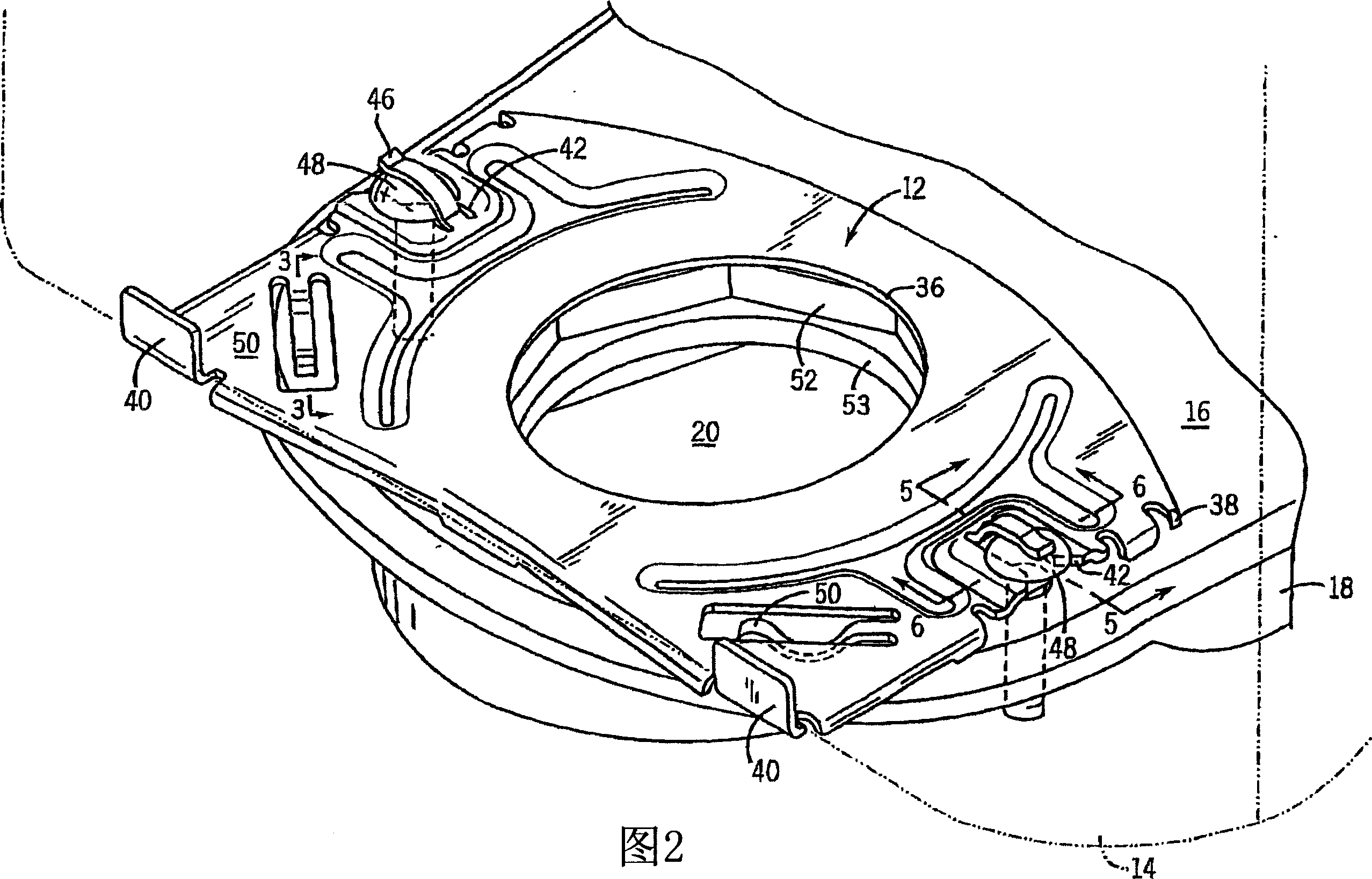
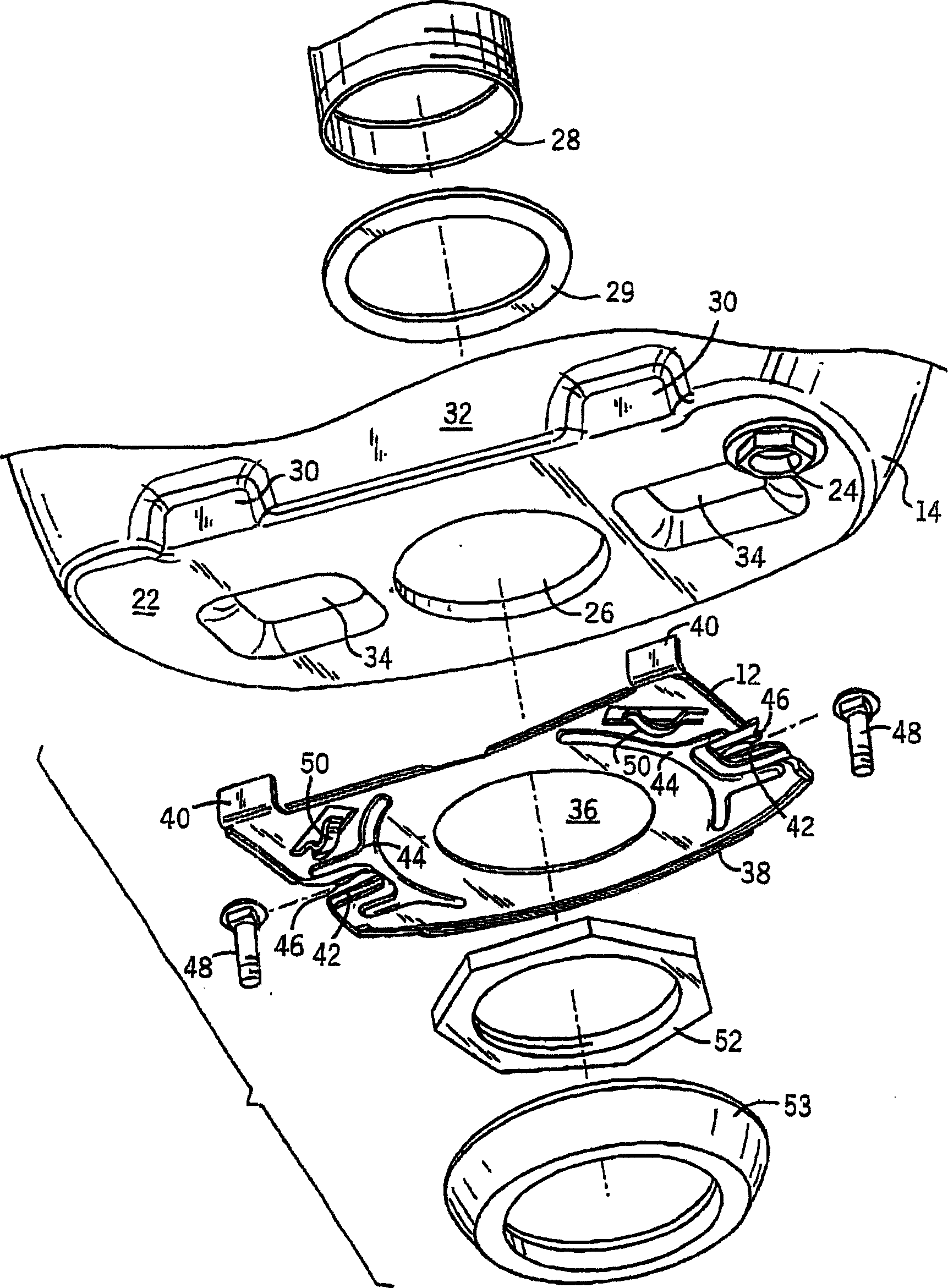
[0030] To attach the tank 14 to the toilet extension 16 of the toilet base 18 for a two-piece toilet (generally indicated at 10) having a bracket 12 according to the present invention, reference should first be made to FIGS. The toilet base 18 and its extension 16 are conventional components, molded from vitreous china or ceramic. As standard, the toilet extension 16 is formed with an opening 20 which leads to the toilet 16 (not shown). The cistern 14 is essentially a standard piece having a bottom wall 22 with a supply inlet 24 and a main flush opening 26 through which an extension 28 of a flush valve (not shown) passes and around which Partially equipped with gasket 29 (see Figure 7 ) to seal the flush port 26. However, the tank 14 also has two sets of recesses, one set of recesses 30 in the rear wall 32 of the tank and another set of recesses 34 in the bottom wall 22 of the tank, for receiving the components described below - the bracket 12 .

[0031] The bracket 12 is ...


PUM


Abstract

An attachment system for mounting a flush tank to a toilet bowl includes a bracket disposed between the tank and the bowl. The bracket has a generally planar body defining a central opening receiving a tubular flush extension extending from the tank into an opening in a bowl extension. The bracket is fastened to the tank by a large nut threaded to the tank extension. The bracket is mounted to the bowl at two slots opening at opposite side edges of the bracket by two bolts disposed through openings in the bowl extension. The bracket has a unitary pair of upwardly extending spring arms contacting the bottom wall of the flush tank and a unitary pair of lower spring arms contacting the bowl extension. The spring arms are deflectable between the flush tank and the toilet bowl to accommodate for warping or mold variations between the tank and the bowl.

Description

[0001] Cross References to Related Applications [0002] Not applicable. [0003] Statement of Federal Support for Research or Development [0004] Not applicable. Background technique [0005] The present invention relates to plumbing fixtures, in particular brackets for connecting a toilet tank to a split toilet seat. [0006] A traditional toilet consists of a toilet and a tank. The toilet and the water tank can be formed integrally or separately. Split toilets are sometimes less expensive to manufacture, and the weight of the toilet can be split in two at the time of purchase, making it easier for consumers to handle. [0007] However, split toilets require the tank to be assembled to the toilet so that the water in the tank can flow into the toilet during the flush cycle. Typically, the bottom wall of the cistern will have a circular opening in the middle through which the tubular portion of the flush valve assembly passes. The tubular extension fits into a correspo...

Claims


Application Information

Patent Timeline
IPC IPC(8): E03D11/00E03D1/26
CPCE03D1/26
Inventor D・N・哈洛伦A・H・马茨尼克M・苏迪皮
Owner KOHLER CO
Why Eureka
Try Eureka