Automatic calibration shield segment

A shield segment and automatic calibration technology, which is applied in wellbore lining, tunnel lining, underground chamber, etc., can solve the problems of increasing installation difficulty, inconvenient calibration, and uneven shield segment.

Inactive Publication Date: 2021-04-20
杨亚玲
View PDF8 Cites 0 Cited by
  • Summary
  • Abstract
  • Description
  • Claims
  • Application Information

AI Technical Summary

Problems solved by technology

[0005] Aiming at the deficiencies of the prior art, the present invention provides an automatic calibration shield segment, which solves the problem of inconvenient calibration during installation of the existing shield segment and increases the difficulty of installation, and can avoid the gap between the shield segments. The joints of the shield ...

Method used


Image

  • Automatic calibration shield segment
  • Automatic calibration shield segment
  • Automatic calibration shield segment

Examples


Embodiment 1

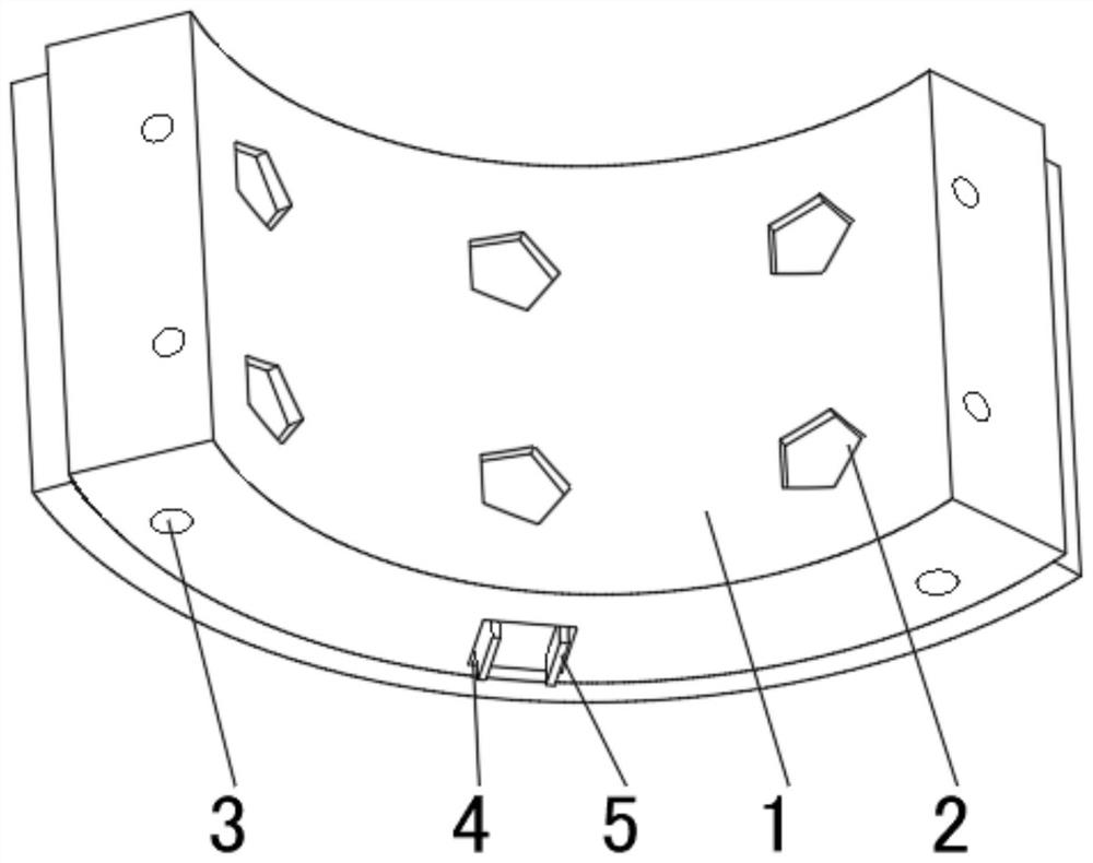
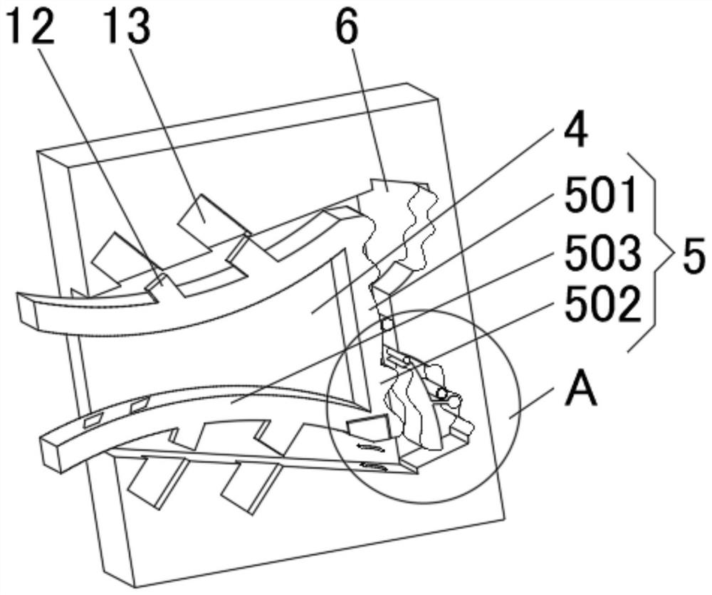
[0030] see Figure 1-4 , the present invention provides a technical solution: an automatic calibration shield segment, including an arc-shaped sheet body 1, an annular groove 2 and a longitudinal groove 3, one side of the arc-shaped sheet body 1 is provided with a calibration groove 4, and the calibration groove 4 It is a table-shaped groove, and one side of the inner wall of the calibration groove 4 is rotatably connected with a positioning frame 5, and the side of the arc-shaped sheet body 1 away from the calibration groove 4 is symmetrically installed with a calibration plate 8, and the calibration plate 8 is an elastic arc-shaped plate.

[0031] The positioning frame 5 includes an arc plate 501, which is rotationally connected to one side of the inner wall of the calibration groove 4, and both ends of the arc plate 501 are fixedly connected with a corrugated rod 502, and the corrugated rod 502 is far away from one end of the arc plate 501 An inner concave plate 503 is fixe...

Embodiment 2

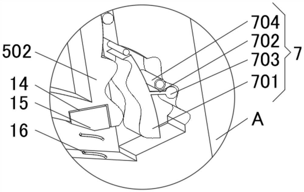
[0035] see Figure 1-4 , the present invention provides a technical solution: on the basis of Embodiment 1, a swing groove 6 is provided symmetrically on one side of the inner wall of the calibration groove 4, and a rectifying device 7 is installed inside the swinging groove 6, and the rectifying device 7 includes extrusion Plate 701, the extruding plate 701 is rotatably connected with the inner wall of the swing groove 6, the radian of the extruding plate 701 is the same as that of the corrugated rod 502, and the side of the extruding plate 701 away from the corrugated rod 502 is fixedly connected with an extruding rod 702. The ball 703 is fixedly connected with a metal pipe 704 on one side of the inner wall of the swing groove 6 .

[0036] When in use, the calibration plate 8 on one side of the newly installed shield segment is aligned into the inside of the clamping frame 5, and when the calibration plate 8 moves to the innermost end of the clamping frame 5, the corrugated ...

Embodiment 3

[0038] see Figure 1-5 , the present invention provides a technical solution: on the basis of Embodiment 1, an anti-skid groove 9 is provided on one side of the calibration plate 8, and an anti-skid device 10 is installed inside the anti-skid groove 9, and the inner wall of the clamping frame 5 is evenly provided with The one-way groove that the anti-slip device 10 is compatible with.

[0039] One side of the inner concave plate 503 is uniformly equipped with inclined blocks 12 , and both sides of the inner wall of the calibration groove 4 are provided with gripping grooves 13 matching with the inclined blocks 12 .

[0040] The anti-skid device 10 includes an anti-skid plate 101, one side of the anti-skid plate 101 is evenly provided with a protective groove 102, both sides of the inner wall of the protective groove 102 are rotatably connected with a laminated plate 103, and the bottom of the laminated plate 103 is fixedly connected with a rubber ball 104.

[0041] One side o...


PUM


Abstract

The invention discloses an automatic calibration shield segment. The segment comprises an arc-shaped segment body, an annular groove and a longitudinal groove, a calibration groove is formed in one side of the arc-shaped segment body, the calibration groove is a table-shaped groove, a clamping frame is rotatably connected to one side of the inner wall of the calibration groove, and swing grooves are symmetrically formed in one side of the inner wall of the calibration groove. Position correcting devices are installed in the swing grooves, and calibration plates are symmetrically installed on the side, away from the calibration groove, of the arc-shaped segment body. The invention relates to the technical field of tunnel construction. According to the automatic calibration shield segment, the purpose of facilitating calibration between shield segments is achieved, the installation difficulty of the shield segments is reduced, unevenness between the shield segments can be avoided, the butt joint position of the shield segments is automatically calibrated, the inspection work after the shield segments are installed is reduced, the tunnel construction efficiency is improved, damage caused by collision between the shield segments is reduced, the service life of a tunnel is prolonged, and the firmness degree of connection between the shield segments is improved.

Description

technical field [0001] The invention relates to the technical field of tunnel construction, in particular to an automatic calibration shield segment. Background technique [0002] At present, tunnel construction methods include open-excavation method and underground excavation method. Among them, the shield tunneling method in the underground excavation method is a fully mechanized construction method. Because the shield tunneling method has the advantages of safe excavation and does not affect the facilities on the ground, it is favored. It is widely used in tunnel construction, such as railway tunnels, highway tunnels, underwater tunnels, underground railways, etc. The shield machine includes the main machine and three supporting frames behind it. The front end of the main machine is a cutter head, and different tools are installed on the cutter head. , the motor drives the rotation of the cutter head, and several groups of hydraulic jacks push the cutter head forward, so ...

Claims


Application Information

Patent Timeline
IPC IPC(8): E21D11/08E21F17/18
Inventor 杨亚玲
Owner 杨亚玲
Why Eureka
Try Eureka