
Detection and control of diaphragm collapse in condenser microphones

一种电容式麦克风、膜片的技术,应用在电气元件、换能器电路、传感器保护电路等方向,能够解决没有公开电容式麦克风破裂检测和控制电路等问题,达到简单定制、大灵活性的效果

Inactive Publication Date: 2006-03-01
TDK CORPARATION
View PDF2 Cites 36 Cited by
  • Summary
  • Abstract
  • Description
  • Claims
  • Application Information

AI Technical Summary

Problems solved by technology

[0006] To the best of the inventor's knowledge, no crack detection and control circuits for use in condenser microphones have been disclosed

Method used


Image

  • Detection and control of diaphragm collapse in condenser microphones
  • Detection and control of diaphragm collapse in condenser microphones
  • Detection and control of diaphragm collapse in condenser microphones

Examples


Embodiment Construction

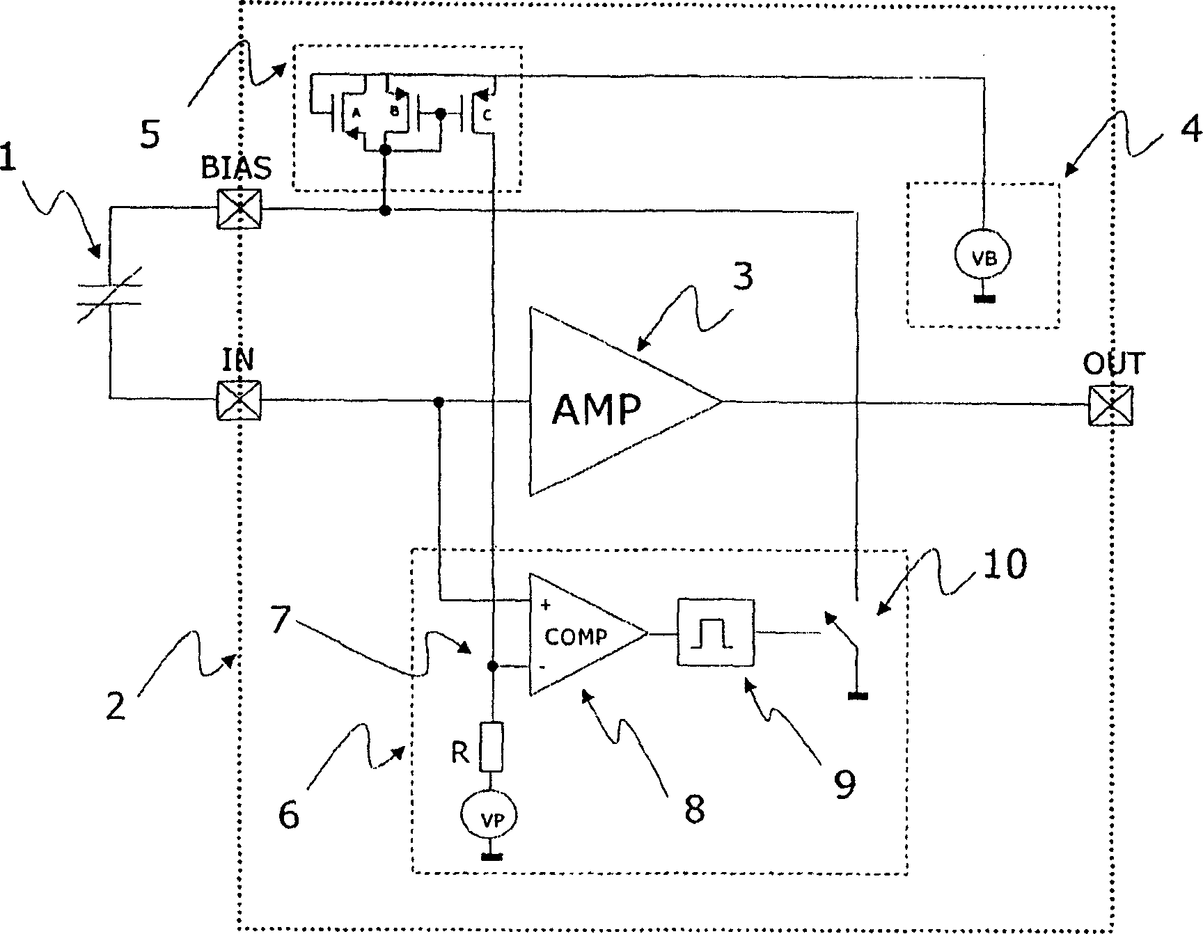
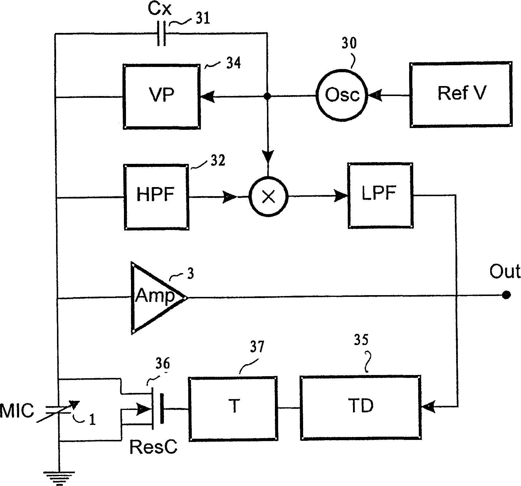
[0040] In the following embodiments, a break detection and control circuit suitable for integration into a small silicon-based condenser microphone will be described.

[0041] Several embodiments of the rupture detection circuit for detecting the distance between the diaphragm and the rear plate can be envisioned. Physical parameters such as voltage, capacitance and sound pressure can be used as described below. The detection circuit preferably makes the transducer element of the condenser microphone not load any significant impedance (relative to the generator impedance of the transducer element itself). The silicon transducer element of a MEMS microphone has a very large impedance, which basically corresponds to a capacitance of 5-20 pF, which makes meeting this requirement a great challenge.

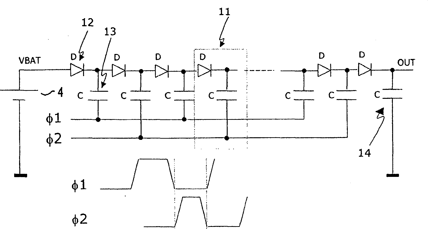
[0042] Several embodiments of the rupture control circuit according to the present invention are also possible, some of them will be described below together with the detection circuit. T...


PUM


Abstract

The invention relates to a condenser microphone comprising detection means adapted to determine the value of a physical parameter with respect to the spacing or distance between the diaphragm of the transducer element and the rear plate, and adapted to control the transducer based on the determined value of the physical parameter. Burst control device for DC biasing of energy element.

Description

Technical field [0001] The invention relates to a condenser microphone, comprising a detection device and a rupture control device. The detection device is suitable for determining physical parameter values ​​related to the distance between a transducer element diaphragm and a rear plate. The rupture control device is suitable for determining The determined physical parameter value controls the DC bias of the transducer element. Background technique [0002] As we all know, under certain operating conditions, electrostatic actuators and sensors, such as when they are exposed to extremely high sound pressure levels and mechanical vibrations, may enter a so-called rupture state that people do not want. [0003] The fractured state is characterized by "cracking" or adhesion between the diaphragm and the rear plate, as described in PCT patent application WO02 / 098166 which discloses silicon transducer elements. When the polarity of sound pressure is introduced, the diaphragm, usually ...

Claims


Application Information

Patent Timeline
Patent Type & Authority Applications(China)
IPC IPC(8): H04R19/04H04R3/00
CPCH04R19/04H04R3/007
Inventor 拉尔斯·J.·斯腾博格詹斯·K.·波尔森阿特·Z.·万霍特恩
Owner TDK CORPARATION
Learn More