A structure and the manufacturing method for friction parts on concrete pump

A friction component, concrete pump technology, applied in the direction of pumps, piston pumps, liquid variable capacity machinery, etc., can solve the problems of waste, low wear rate, high maintenance cost and resources, etc.

Inactive Publication Date: 2006-03-01
韩乐洙
View PDF0 Cites 9 Cited by
  • Summary
  • Abstract
  • Description
  • Claims
  • Application Information

AI Technical Summary

Problems solved by technology

[0010] It is therefore an object of the present invention to provide a sliding structure for a concrete pump which has a low wear rate by forming the wear areas of the fixed and movable parts with very wear-resistant tungsten carbide; the invention also provides a A method for manufacturing a sliding structure, therefore, the sliding structure of the present invention can solve the problems of high maintenance cost and waste of resources caused by frequent replacement of fixed parts and movable parts, and can provide a relatively low cost with a long service life life sliding structure

Method used


Image

  • A structure and the manufacturing method for friction parts on concrete pump
  • A structure and the manufacturing method for friction parts on concrete pump
  • A structure and the manufacturing method for friction parts on concrete pump

Examples


Embodiment Construction

[0030] Through the following description of the embodiments with reference to the drawings, other objects and aspects of the present invention will be clearly understood.

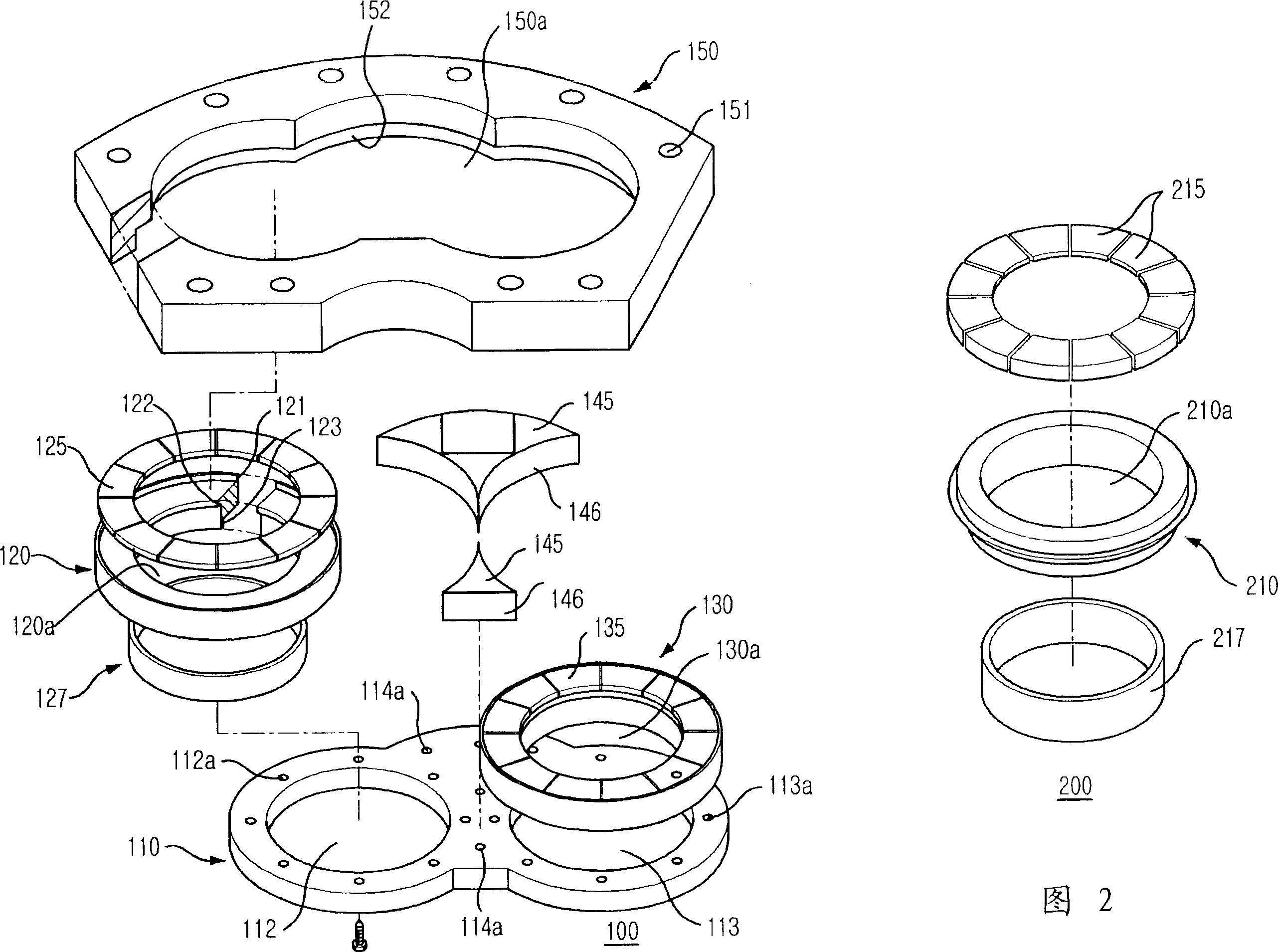
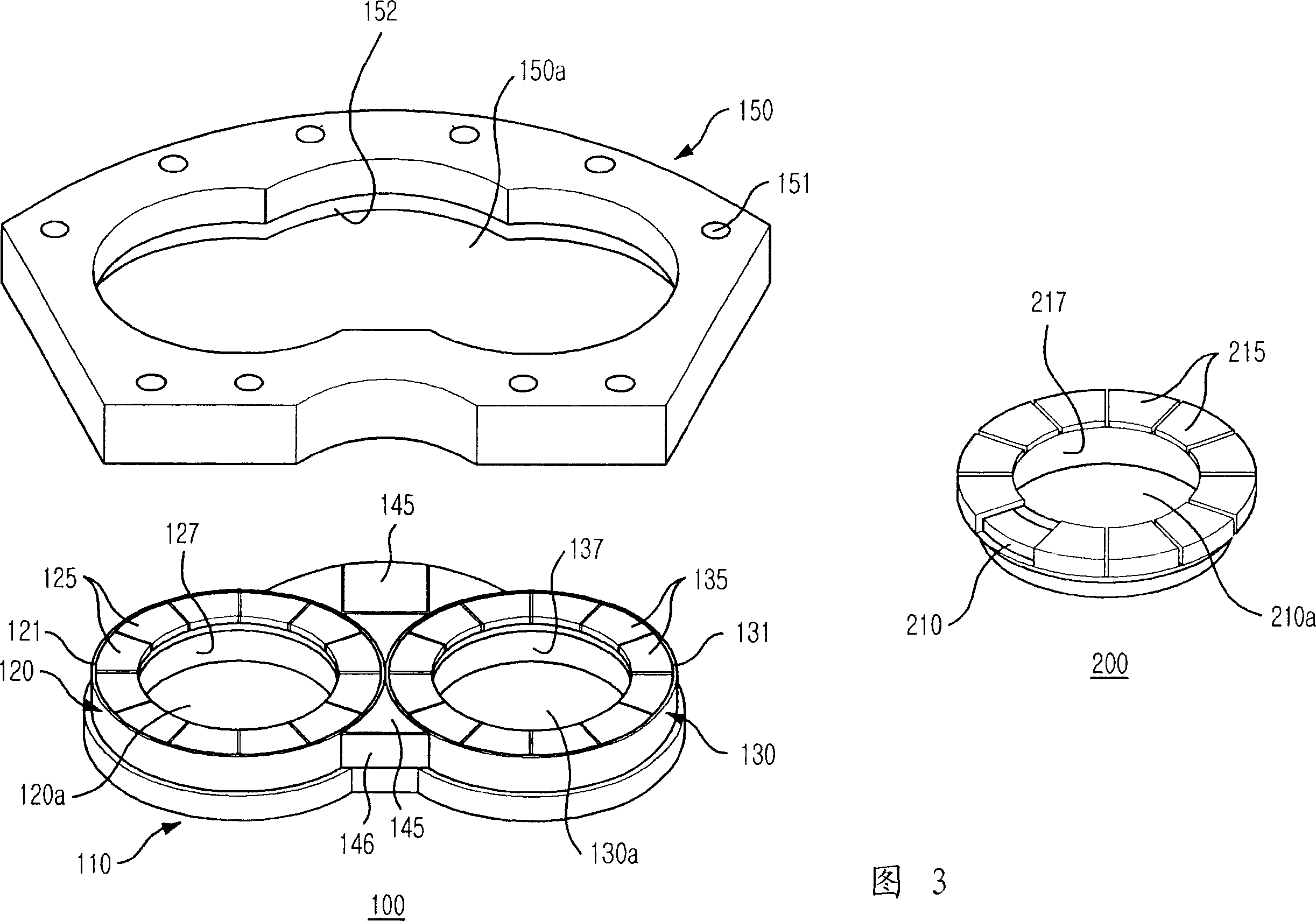
[0031] Fig. 2 is an exploded perspective view showing the sliding structure of the embodiment of the present invention. Fig. 3 is a perspective view showing the sliding structure of Fig. 2, Figure 4 It is a cross-sectional view showing a side part of the sliding structure of FIG. 3. The sliding structure for a concrete pump includes: a flat fixed part 100 with a pair of inlet holes 120a and 120b; and an annular movable part 200 with an outlet hole 210a.

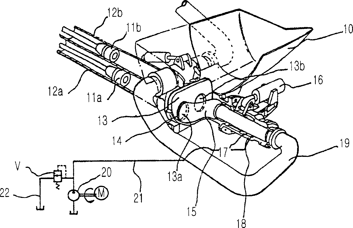
[0032] The concrete pump extrudes concrete by using concrete pistons that alternately move back and forth in a pair of concrete cylinders, and discharges the concrete through an S-shaped gate valve. The extruded concrete is shaken in the S-shaped gate valve, and the fixed part 100 and the movable part 200 are firmly fixed. At the end of the concrete cylinder ...


PUM


Abstract

The present invention relates to a sliding motion structure for a concrete pump that can reduce the extent of abrasion and solve the problem of high maintenance expenses resulting from frequency replacement of the sliding motion structure by fabricating friction areas with a plurality of wear-resistant friction blocks, and to a manufacturing method thereof. Also, the sliding motion structure and the manufacturing method thereof can also prevent the internal wall surfaces of the inlet ports and outputs, through which concrete is transferred, from being worn out and prevent the external end of the connecting pipe from being worn out partially. The sliding motion structure of the present research includes a plane fixed member having a wear plate, a pair of coupling tubes, first friction members, and a second friction member; and a ring-shaped movable member having a ring-shaped connecting pipe and a third friction member which is formed of tungsten carbide and connected to the first and second friction members tightly along the ends of the connecting pipe in the same length.

Description

Technical field [0001] The present invention relates to a concrete pump, in particular to a sliding structure used in a concrete pump and a method for manufacturing it, wherein the sliding structure can be manufactured with a plurality of wear-resistant friction blocks in the friction area of ​​the sliding structure, and Solve the problem of high maintenance cost due to frequent replacement, and prevent the inner wall of the inlet / outlet hole of the concrete from being worn out and the outer end of the coupling pipe from being unevenly worn, thereby reducing their wear rate. Background technique [0002] figure 1 It is a perspective view of an example of a traditional concrete pump. As shown in the figure, there are a pair of concrete cylinders 12a and 12b. The concrete pistons 11a and 11b are installed in the pair of concrete cylinders 12a and 12b, respectively. 13 is connected to the outlet holes of the concrete cylinders 12a and 12b, and the inlet holes 13a and 13b of the fi...

Claims


Application Information

Patent Timeline
Patent Type & Authority Applications(China)
IPC IPC(8): F04B15/02F04B7/00
CPCF04B15/023F04B7/0026F04B15/02
Inventor 韩乐洙
Owner 韩乐洙
Why Eureka
Try Eureka