Rotary abaculus valveless piezoelectric pump

A technology of valveless piezoelectric pumps and inserts, which is applied in the direction of pumps, pumps with flexible working elements, liquid displacement machinery, etc., and can solve the problem of not being able to change the direction of fluid flow.

Inactive Publication Date: 2006-03-08
BEIJING UNIV OF TECH
View PDF0 Cites 7 Cited by
  • Summary
  • Abstract
  • Description
  • Claims
  • Application Information

AI Technical Summary

Problems solved by technology

This method not only requires a complex frequency conversion circuit to control the pump flow, but also cannot change the flow direction of the fluid

Method used


Image

  • Rotary abaculus valveless piezoelectric pump
  • Rotary abaculus valveless piezoelectric pump
  • Rotary abaculus valveless piezoelectric pump

Examples


Embodiment Construction

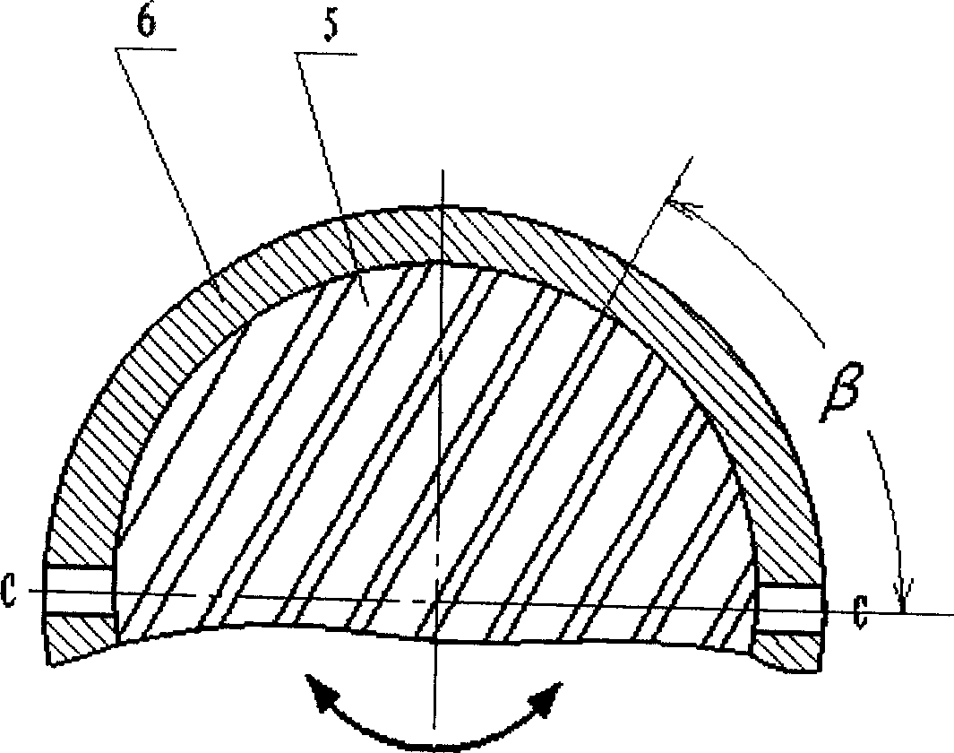
[0027] The structure of the embodiment of the present invention is shown in Figure 6, the piezoelectric vibrator is 30mm; the working power supply is 220V, 50Hz alternating current; the α of the piezoelectric vibrator 1 =90°, α 2 =30°, when the number of corrugations n=4, water is used as the working medium for the experiment, and the left and right flow channels of the pump generate a water column with a maximum pressure difference of 6mm.

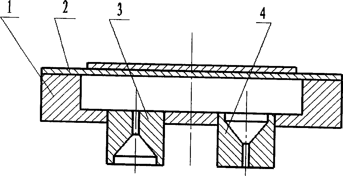
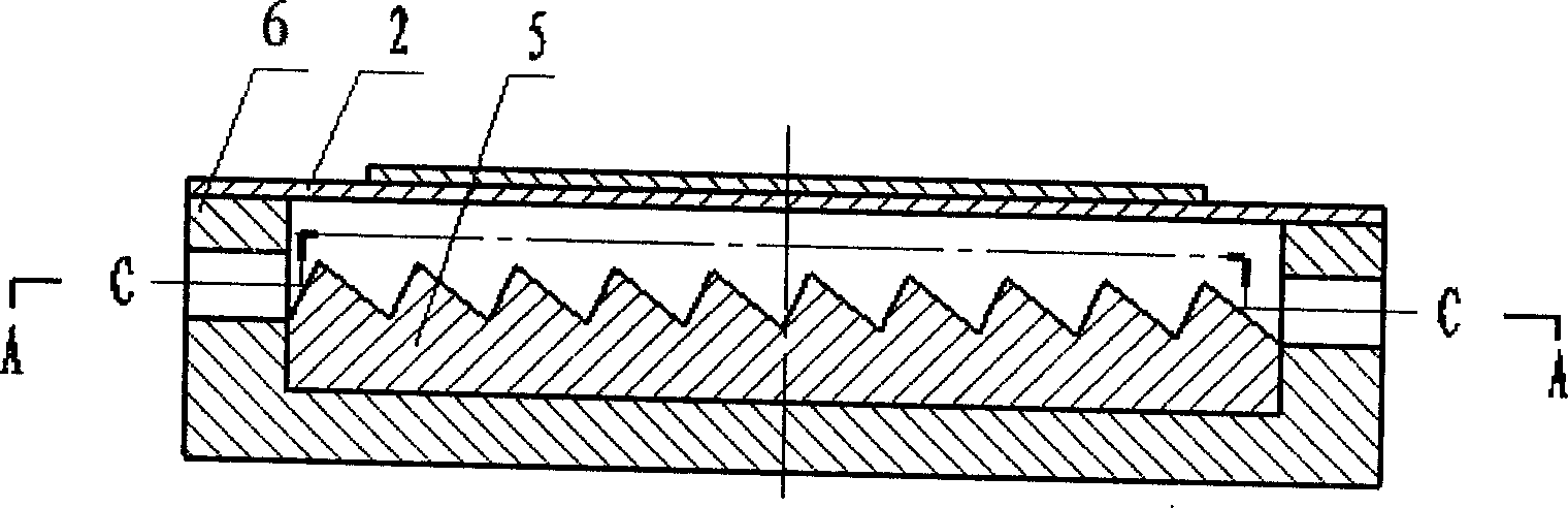
[0028] The conduit 9 is fixed on the upper cover 10 of the pump cavity with commercially available sealant, the sealing cover 7 and the upper cover 10 are fixed with fixing plate screws 8, and the rotating insert 5 and the pump body 6 are fitted with clearance before the upper cover 10 is installed. Assembled together in the same way, the embedded magnet 12 is glued in the rotating insert 5, and the upper cover 10 and the pump chamber 6 are fastened together with screws 11. The piezoelectric vibrator 2 is a commercially available non-sta...


PUM


Abstract

A pressure free electric pump with changeable flow and direction, which contains piezoelectric vibrator, rotary embedded block, every corrugated unit consisting of crossed planes, corrugated unit and piezoelectric vibrator constructing taper flow pipe, two planes intersecting line of corrugated unit is corrugated line paralleled each other, the embedded block rotating in cavity, the dip angle of corrugated line with suction inlet and outlet axis can be change from 0 degree to 360 degree, which resulting the taper angle of taper flow pipe changing, so the flow and direction are changed only by rotating the embedded block in pump cavity without auxiliary frequency change circuit.

Description

technical field [0001] The invention belongs to the field of fluid machinery, and relates to a valveless piezoelectric pump with rotary inserts. Background technique [0002] Piezoelectric pumps belonging to the volumetric type can be divided into valved and valveless piezoelectric pumps if they are classified according to the valve body. If the valve is defined as: during the suction and discharge process of the pump, at least for a moment, there is a mechanical device that is not connected between the pump chamber and the suction port or the discharge center, then the so-called "valveless" means: at any time , The pump cavity is connected with the inlet or outlet. At this time, the one-way flow of fluid relies on special mechanical devices. This device utilizes the properties of the fluid, so that the pump chamber is always in communication with the suction and discharge ports, and can drive the fluid to flow in one direction. At present, valveless piezoelectric pumps m...

Claims


Application Information

Patent Timeline
Patent Type & Authority Applications(China)
IPC IPC(8): F04B43/04F04B45/047
Inventor 张建辉夏齐霄路计庄
Owner BEIJING UNIV OF TECH
Why Eureka
Try Eureka