Backlight assembly and liquid crystal display device using the same

A bolt and cooling medium technology, applied in the field of bolts, can solve problems such as temperature reduction, and achieve the effect of eliminating direct influence

Inactive Publication Date: 2004-03-31
SIEMENS AG
View PDF0 Cites 5 Cited by
  • Summary
  • Abstract
  • Description
  • Claims
  • Application Information

AI Technical Summary

Problems solved by technology

As a result, the temperature in the combustion chamber is undesirably lowered

Method used


Image

  • Backlight assembly and liquid crystal display device using the same
  • Backlight assembly and liquid crystal display device using the same
  • Backlight assembly and liquid crystal display device using the same

Examples


Embodiment Construction

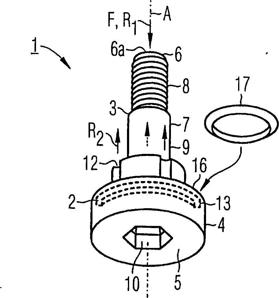
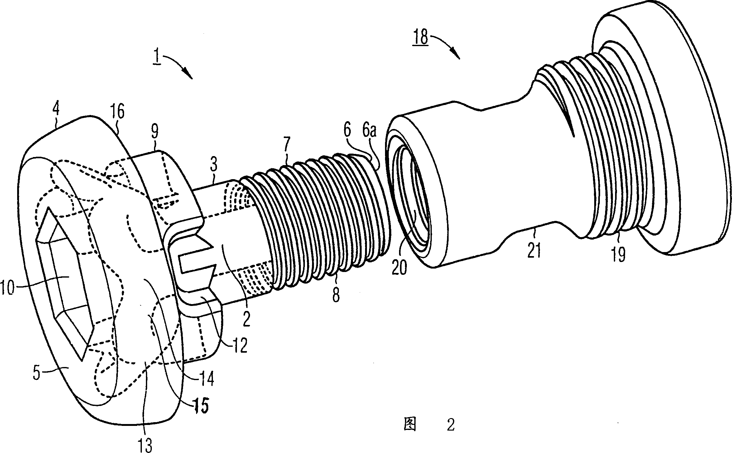
[0017] Figure 1a An internally-coolable screw 1 is shown, the cooling medium channel or cooling channel 2 is cut out in the Figure 1b shown in. The screw 1 has a threaded rod 3 and a nut 4 and extends along an axis or axis of symmetry A from the cover surface 5 of the nut 4 , which is located below in the illustration, to the screw end 6 . The threaded rod 3 has a thread 8 on its outer circumference 7 and a thickened screw flange 9 which delimits the threaded rod 3 in the direction of the nut 4 . The nut 4 has, on its cover surface 5, a hexagonal operating hole 10 for an Allen key.

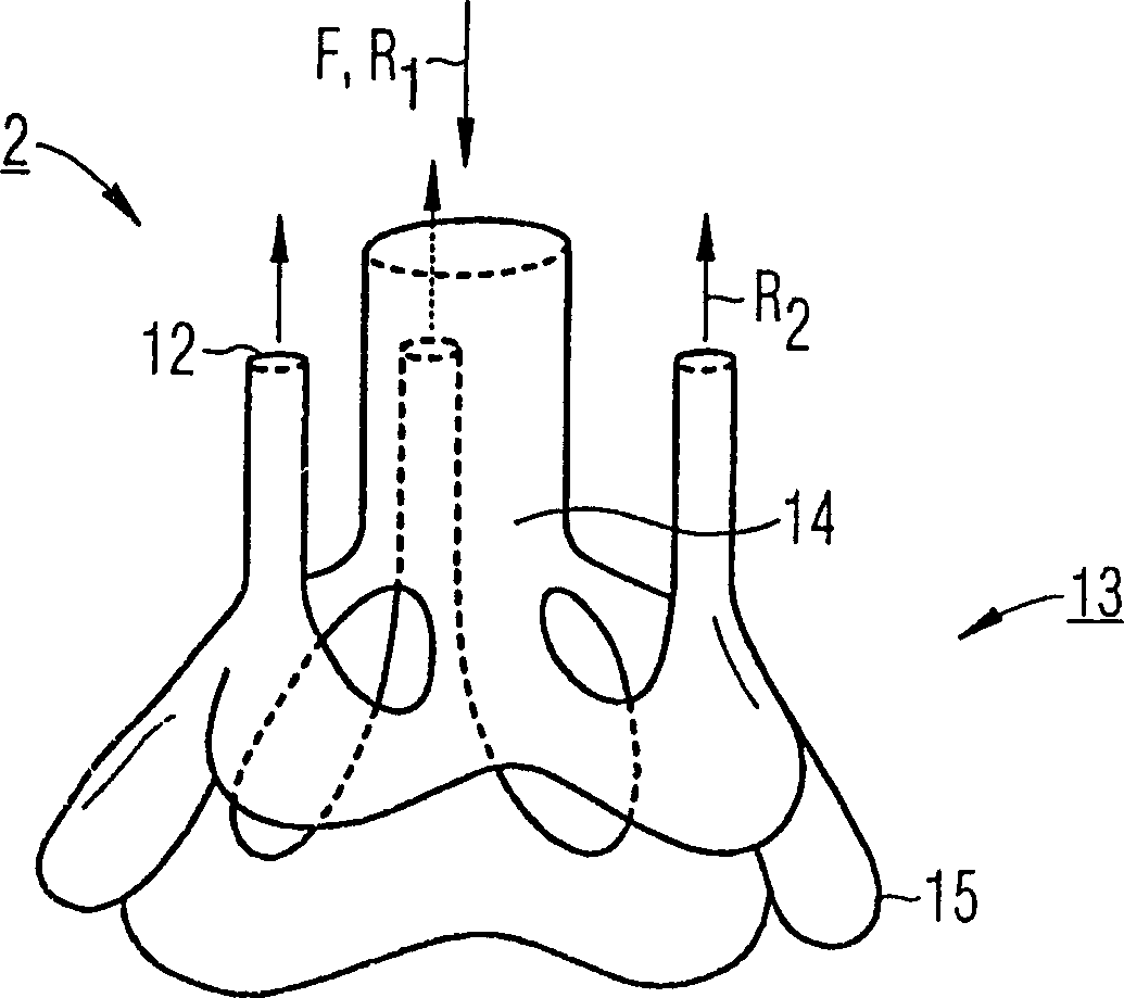
[0018] The cooling medium or cooling fluid F flows in the axial direction of the screw end 6 in the inflow direction R1 into the inflow opening 6a of the screw 1 and from there from the three cooling medium outflow openings 12 in the outflow direction R2 which is directed opposite to the inflow direction R1 outflow. The cooling channel 2 first extends axially coaxially with the screw 3 and th...


PUM


Abstract

A screw includes a head and a shank, and includes a coolant passage which has an inflow opening and an outflow opening. The cooling pasage does not pass axially through the entire head and shank. By avoiding a coolant flow which passes axially through the entire screw, especially effective utilization of a coolant is achieved, in particular by coolant which also flows on the outer surface of the screw.

Description

technical field [0001] The invention relates to a bolt which can be internally cooled by a flowing cooling medium. Background technique [0002] For example, some bolts that are subjected to high mechanical and thermal loads are used in gas turbines. An example of an application is for securing a combustion chamber liner to a wall of a combustion chamber. In order to obtain a high efficiency, it is usually attempted to drive a gas turbine by having a temperature in the combustion chamber as high as possible. Typically, the gas temperature at the combustor outlet reaches 1200°C to 1300°C. The combustion chamber lining is usually fastened to the combustion chamber wall by means of bolts inserted from the inside, ie from the combustion chamber. Therefore, the nut is directly exposed to the gas in the combustion chamber. If the bolts or parts of the bolts, in particular the nuts, enter the combustion chamber due to bolt failure and are carried away with the gas flow, serious...

Claims


Application Information

Patent Timeline
Patent Type & Authority Applications(China)
IPC IPC(8): F01D25/12F02C7/18F16B33/00F16B35/00F16B35/04F16B35/06F23R3/42F23R3/60
CPCF16B35/06F16B33/00F16B35/04F23R3/60F16B35/044
Inventor 彼得·蒂曼
Owner SIEMENS AG
Why Eureka
Try Eureka