A guide vane type rotary jet pump

A jet flow and guide vane technology, applied in the field of jet pumps, can solve the problems of low energy exchange efficiency and small momentum exchange, and achieve the effect of improving energy exchange efficiency and flow ratio

Inactive Publication Date: 2011-12-28
CHINA AGRI UNIV
View PDF6 Cites 5 Cited by
  • Summary
  • Abstract
  • Description
  • Claims
  • Application Information

AI Technical Summary

Problems solved by technology

However, the jet pump mainly relies on the development of the turbulent mixing layer to realize the fluid energy exchange of different energies, and the mixing layer can basically be regarded as axisymmetric, that is, the velocity in the circumferential direction is very small, the velocity gradient is almost zero, and the momentum exchange Very small, so the energy exchange efficiency is low

Method used


Image

  • A guide vane type rotary jet pump
  • A guide vane type rotary jet pump
  • A guide vane type rotary jet pump

Examples


Embodiment Construction

[0011] The present invention will be described in detail below in conjunction with the accompanying drawings and embodiments.

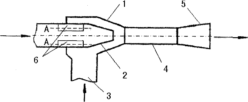
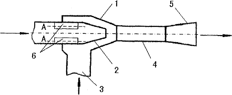
[0012] Such as figure 1 As shown, the present invention includes a head 1, a nozzle 2 is arranged in one end along the horizontal direction of the head 1, and the working fluid flows in from the nozzle 2; an inlet 3 for the suctioned fluid to enter is arranged along the bottom of the head 1 in the vertical direction . The other end along the horizontal direction of the head 1 is connected to a diffuser 5 through a throat 4 , and the mixed fluid after mixing the working fluid and the sucked fluid flows out from the diffuser 4 . Wherein, a group of guide vanes 6 are arranged on the inner wall of the nozzle 2 to provide a peripheral velocity for the working fluid, so that the working fluid flows out of the nozzle 2 to form a certain peripheral velocity around the axis of the nozzle 2 .

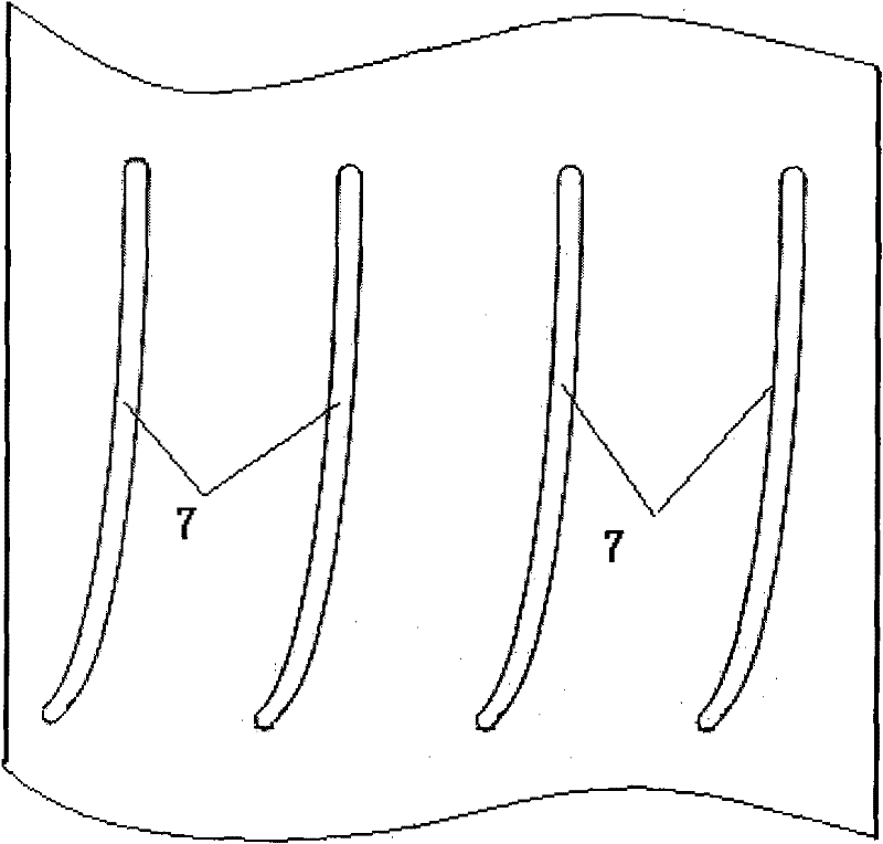
[0013] Such as figure 2 As shown, in the above-mentioned embodi...


PUM


Abstract

The invention relates to a guide vane type rotary jet pump, which is characterized in that it comprises a head, a nozzle is arranged in one end along the horizontal direction of the head, and an inlet is arranged in the bottom along the vertical direction of the head; The other end of the head in the horizontal direction is connected to a diffuser through a throat; a group of guide vanes capable of providing peripheral speed are arranged on the inner wall of the nozzle. Since the present invention adopts a set of guide vanes on the inner wall of the nozzle, the working fluid flowing in from the nozzle passes through the guide vanes, so that the working fluid flows out of the nozzle and has a certain circumferential speed around the axis of the nozzle, thus changing the flow rate of the working fluid. The turbulent flow structure of the mixed layer with the absorbed fluid improves the energy exchange efficiency between the operating fluid and the absorbed fluid. The invention can be widely applied under various complicated working conditions.

Description

technical field [0001] The invention relates to a jet pump, in particular to a guide vane type rotary jet pump. Background technique [0002] Since the jet pump itself has no moving parts, it has many advantages such as simple structure, reliable operation, easy processing, good sealing, convenient maintenance and management, and comprehensive utilization. Especially under special working conditions such as high temperature, high pressure, vacuum, strong radiation and underwater, the jet pump can greatly simplify the entire process and equipment. However, the jet pump mainly relies on the development of the turbulent mixing layer to realize the fluid energy exchange of different energies, and the mixing layer can basically be regarded as axisymmetric, that is, the velocity in the circumferential direction is very small, the velocity gradient is almost zero, and the momentum exchange Very small, so the energy exchange efficiency is low. Contents of the invention [0003] ...

Claims


Application Information

Patent Timeline
Patent Type & Authority Applications(China)
IPC IPC(8): F04F5/00
Inventor 周凌九严海军
Owner CHINA AGRI UNIV
Why Eureka
Try Eureka