
Patsnap Eureka
For R&D, Patsnap Eureka makes reading and utilizing patents & technical documents easy.
Patsnap Eureka AIR
Designed for self-driven R&D workflows. Generate viable solutions, solve complex R&D challenges, empower your innovation with AI.

Patsnap Eureka Materials
Designed for material experts only. Revolutionize your material R&D, from search, analyze, to developing new materials.

TechResearch
Generate reliable direction feasibility study reports for your R&D in just a few steps.

TechSeek
Discover and master advanced knowledge NOW. Basics, ideas, possibilities, all at once.

TechMind
As an expert in R&D Theories, TechMind can generates customized viable solutions instantly.

TechRisk
Analyze your overall solution with one click, know your potential R&D risks in advance.

TechMonitor
Get weekly tech updates, stay abreast of the latest tech innovations and key insights.
Diameter-variable nozzle stub throat process
A technology of short tube and necking, which is applied in the field of variable diameter short tube shrinking technology, can solve the problems of expensive mold cost, difficult quality assurance, low production efficiency, etc., and achieve the effect of fast processing and simple process
- Summary
- Abstract
- Description
- Claims
- Application Information
AI Technical Summary
Problems solved by technology
Method used
Image

Examples
Embodiment 1
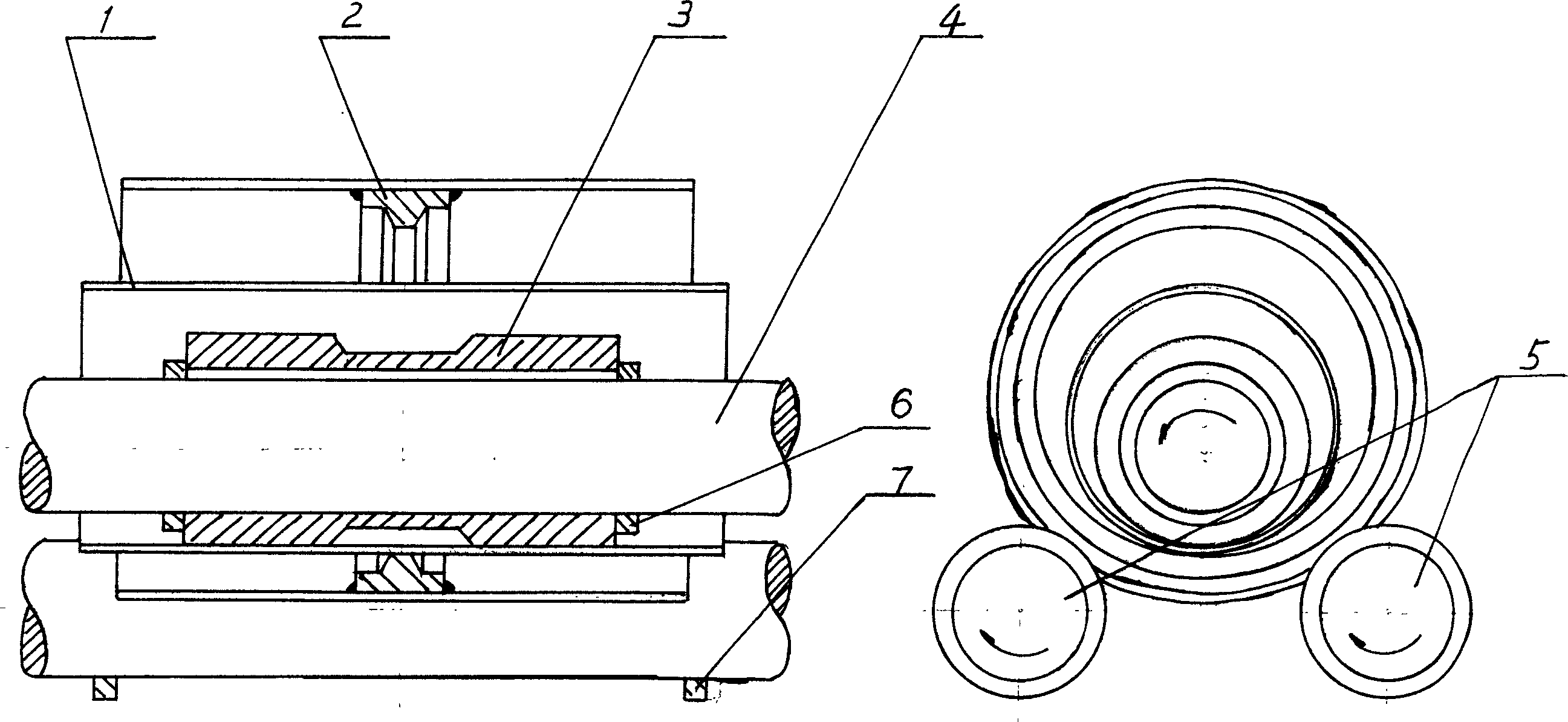
[0009] Embodiment 1, using a three-axis rolling machine to process a short pipe with reduced diameter:
[0010] Refer to attached figure 1 The lining mold 3 adopts a garden cylinder with a groove in the middle of the outer wall, and the punch 2 adopts a garden cylinder with a circular protrusion in the middle of the inner wall. The punch 2 is set outside the lifting roller 4, and is driven by two active rollers. Hold the shaft 5, install the punch limit ring 7 on both ends of the punch 2 on the active roller 5, then set the lining mold 3 on the lifting roller 4, adjust the installation position of the lining mold 3, so that the lining mold 3 Align the centerline of the center line with the center line of the punch 2, install the liner limit ring 6 at both ends of the liner 3 on the lifting roller 4, and then set the pipe material 1 to be processed on the liner 3, and align center. At this time, start the roller bed lifting mechanism, make the lifting roller 4 slowly descend,...
Embodiment 2
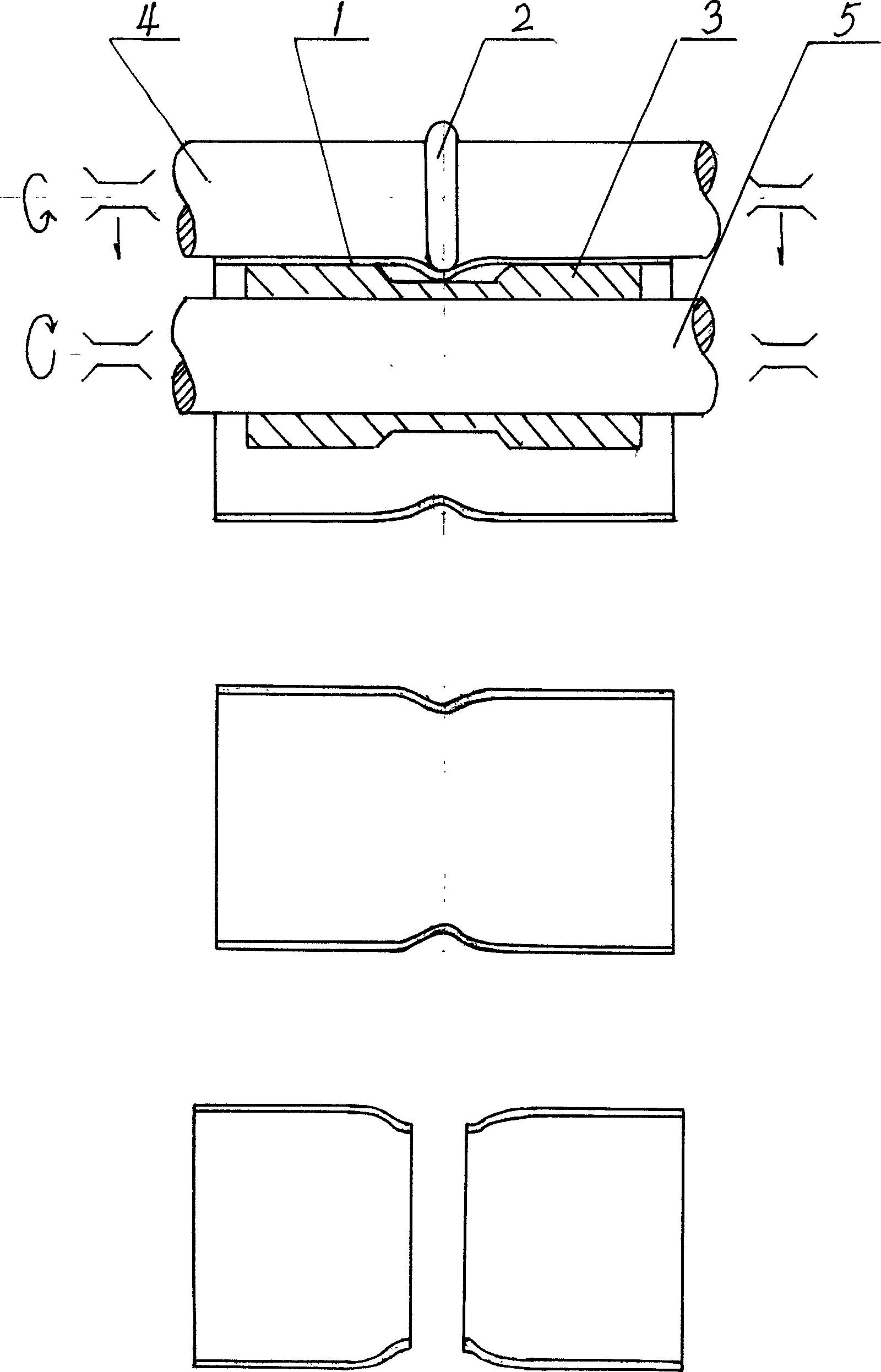
[0011] Embodiment 2, using two-roller universal rolling machine to process variable-diameter short pipe:
[0012] Refer to attached image 3 , the lining mold 3 adopts a garden cylinder with grooves in the middle of the outer wall, the punch 2 adopts a circular punch, the punch 2 is set on the lifting roller 4, the lining mold 3 is set on the driving roller 5, and the The center line is aligned with the center line of the punch 2, and the pipe material 1 to be processed is set on the lining die 3 to find the center. At this time, start the roller bed lifting mechanism, make the lifting roller 4 slowly descend, press the pipe material 1, then start the roller bed, make the two driving rollers 5 rotate, and drive the lining mold 3, pipe material 1 and punch 2 to rotate , at the same time, the lifting roller 4 continues to descend slowly. At this time, after the tube material 1 is subjected to the strong radial rolling action of the circular protrusion of the punch 2, the pressu...
Embodiment 3
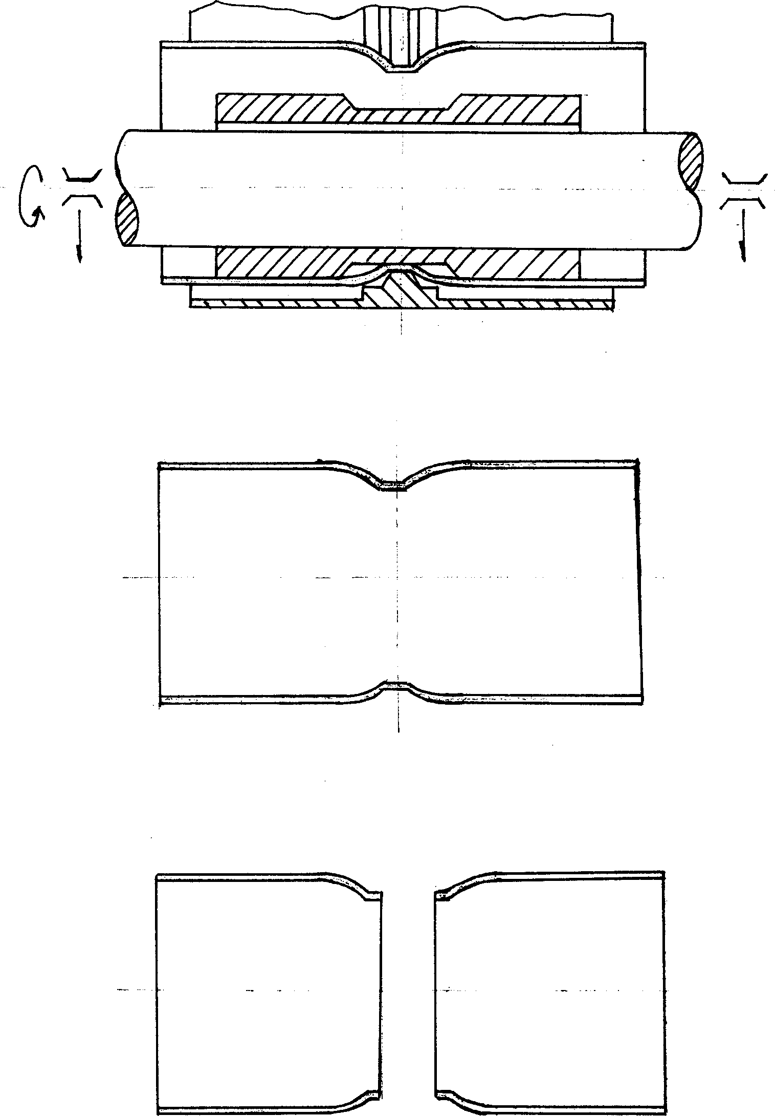
[0013] Embodiment 3, using a three-axis rolling machine to process a short pipe with reduced diameter:
[0014] Refer to attached Figure 4 , the lining mold 3 adopts a cylindrical shape, and the length of the lining mold 3 is less than the length of the pipe material 1 to be processed. The punch 2 adopts a garden cylinder with circular protrusions on the inner walls of both ends. Outside the roller 4, and supported by two active rollers 5, the lining mold 3 is set on the lifting roller 4, and the installation position of the lining mold 3 is adjusted so that the center line of the lining mold 3 and the center of the punch 2 Line alignment, and then set the pipe material 1 to be processed on the lining mold 3, and find the center. At this time, start the roller bed lifting mechanism, make the lifting roller 4 slowly descend, press the pipe material 1, then start the roller bed, make the two driving rollers 5 rotate, and drive the punch 2, the lining mold 3 and the pipe materi...
PUM
 Abstract
Description
Claims
Application Information
 - R&D Engineer
- R&D Manager
- IP Professional
- Industry Leading Data Capabilities
- Powerful AI technology
- Patent DNA Extraction
Browse by: Latest US Patents, China's latest patents, Technical Efficacy Thesaurus, Application Domain, Technology Topic, Popular Technical Reports.
© 2024 PatSnap. All rights reserved.Legal|Privacy policy|Modern Slavery Act Transparency Statement|Sitemap|About US| Contact US: help@patsnap.com