Method for manufacturing piezoelectric resonator

A piezoelectric resonator and resonator technology, applied in electrical components, impedance networks, etc., can solve problems such as depolarization of piezoelectric substrates

Inactive Publication Date: 2006-03-15
MURATA MFG CO LTD
View PDF2 Cites 5 Cited by
  • Summary
  • Abstract
  • Description
  • Claims
  • Application Information

AI Technical Summary

Problems solved by technology

In other words, it is possible to...

Method used


Image

  • Method for manufacturing piezoelectric resonator
  • Method for manufacturing piezoelectric resonator
  • Method for manufacturing piezoelectric resonator

Examples


Embodiment Construction

[0048] The present invention will be described in detail below by describing preferred embodiments in conjunction with the accompanying drawings.

[0049] first preferred embodiment

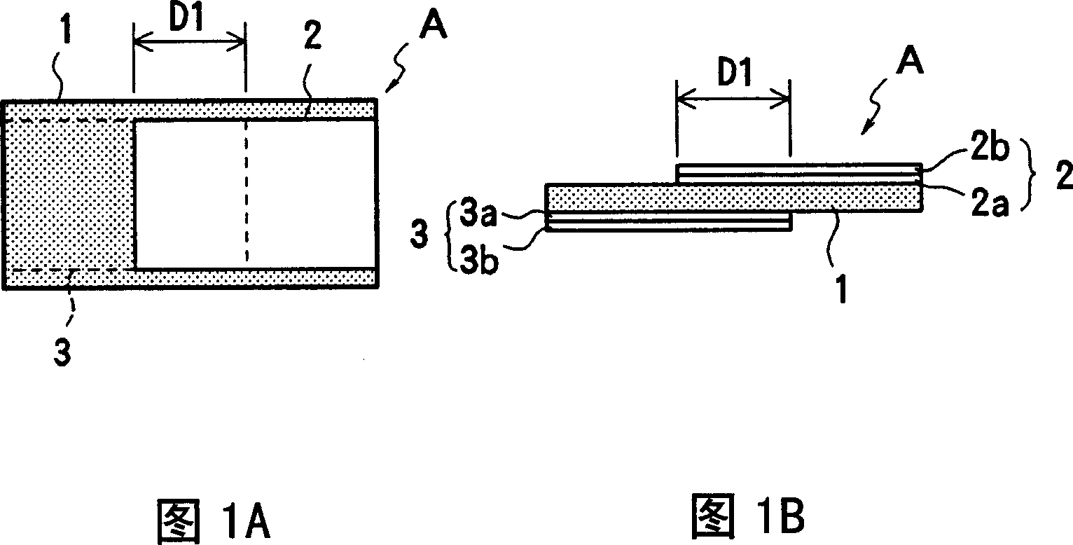
[0050] 1A to 4B show the manufacturing flow of the piezoelectric resonator of the first preferred embodiment of the present invention. The piezoelectric resonator of this preferred embodiment is a two-terminal resonator.

[0051] Resonator A is shown in the first stage of the manufacturing process in FIGS. 1A and 1B . The resonator A includes a rectangular piezoelectric substrate 1, and first electrodes 2 and 3 formed on the front and back surfaces of the piezoelectric substrate 1, respectively. The resonator A is preferably an energy-trap thickness-shear vibration mode resonator, and is polarized on the front and back surfaces of the piezoelectric substrate 1 in parallel directions. One end of the first electrode 2 and one end of the first electrode 3 are opposed to each other at approximatel...


PUM


Abstract

A method of manufacturing a piezoelectric resonator includes forming first electrodes larger than vibrating electrodes in an area D 1 including the vibrating electrodes on obverse and reverse surfaces of a piezoelectric substrate, and measuring the resonant frequency fr<1>of a resonator including the first electrodes. The thickness of a metallic thin film required for frequency adjustment is determined based on the measured resonant frequency. Then, second electrodes formed of the metallic thin film having the determined thickness are formed in an area D 2 including at least the vibrating electrodes of the piezoelectric substrate. By removing unnecessary portions of the first and second electrodes, a pattern of the resulting vibrating electrodes is formed. Thus, high-accuracy frequency adjustment can be achieved without the need for complicated positioning.

Description

technical field [0001] The present invention relates to a method of manufacturing a piezoelectric resonator in which vibrating electrodes are located on both surfaces of a piezoelectric substrate and piezoelectric vibration is confined between the vibrating electrodes, and more particularly, the present invention relates to a A method of adjusting the frequency of a piezoelectric resonator. Background technique [0002] In recent years, in the field of piezoelectric resonators such as those used in oscillators and filters, there has been an increasing demand for precise frequency adjustment. Previously, ink was applied to the electrodes, and the frequency was adjusted by the inertial loading of the electrodes. However, in this method, the amount of ink used varies greatly and the frequency density is low, so the frequency cannot be precisely adjusted. [0003] In order to solve this problem, Japanese Unexamined Patent Application Publication No. 5-29864 discloses a frequen...

Claims


Application Information

Patent Timeline
IPC IPC(8): H03H3/04H03H9/125
Inventor 森村哲也池田吉宏入江诚松下基宪
Owner MURATA MFG CO LTD
Why Eureka
Try Eureka