Motor manufacturing line and its control method

A production line and motor technology, applied in the manufacture of stator/rotor bodies, etc., can solve the problems of large-scale storage space in inventory warehouses, rising management costs, manufacturing costs, and storage time, etc., to shorten delivery time, reduce manufacturing costs, The effect of reducing delivery time

Inactive Publication Date: 2006-03-15
AISIN AW CO LTD
View PDF1 Cites 9 Cited by
  • Summary
  • Abstract
  • Description
  • Claims
  • Application Information

AI Technical Summary

Problems solved by technology

[0009] However, when producing a variety of motors in small quantities, the number and types of rotor cores and stator cores in stock will inevitably expand if the above-mentioned conventional motor manufacturing line is used, and the storage space required for the inventory warehouse will increase in size.
In addition, the storage time of the rotor core and the stator core is prolonged, and the deterioration of the quality characteristics such as the deterioration of the insulation characteristics due to rust, foreign matter, etc.
[0010] In addition, as the storage time in the inventory warehouse increases, the chances of changing the placement, changing the costume, etc. also increase, and the possibility of causing bad deformation will also increase.
In addition, as measures to suppress the above-mentioned deterioration of quality, for example, antirust treatment, storage in a storage box, etc. are required, and there is also an increase in manufacturing costs due to management costs caused by this.
[0011] Also, as mentioned above, since the storage time of the rotor core and the stator core increases, the delivery time from the start of production to the completion is very long, causing various disadvantages

Method used


Image

  • Motor manufacturing line and its control method
  • Motor manufacturing line and its control method
  • Motor manufacturing line and its control method

Examples


Embodiment

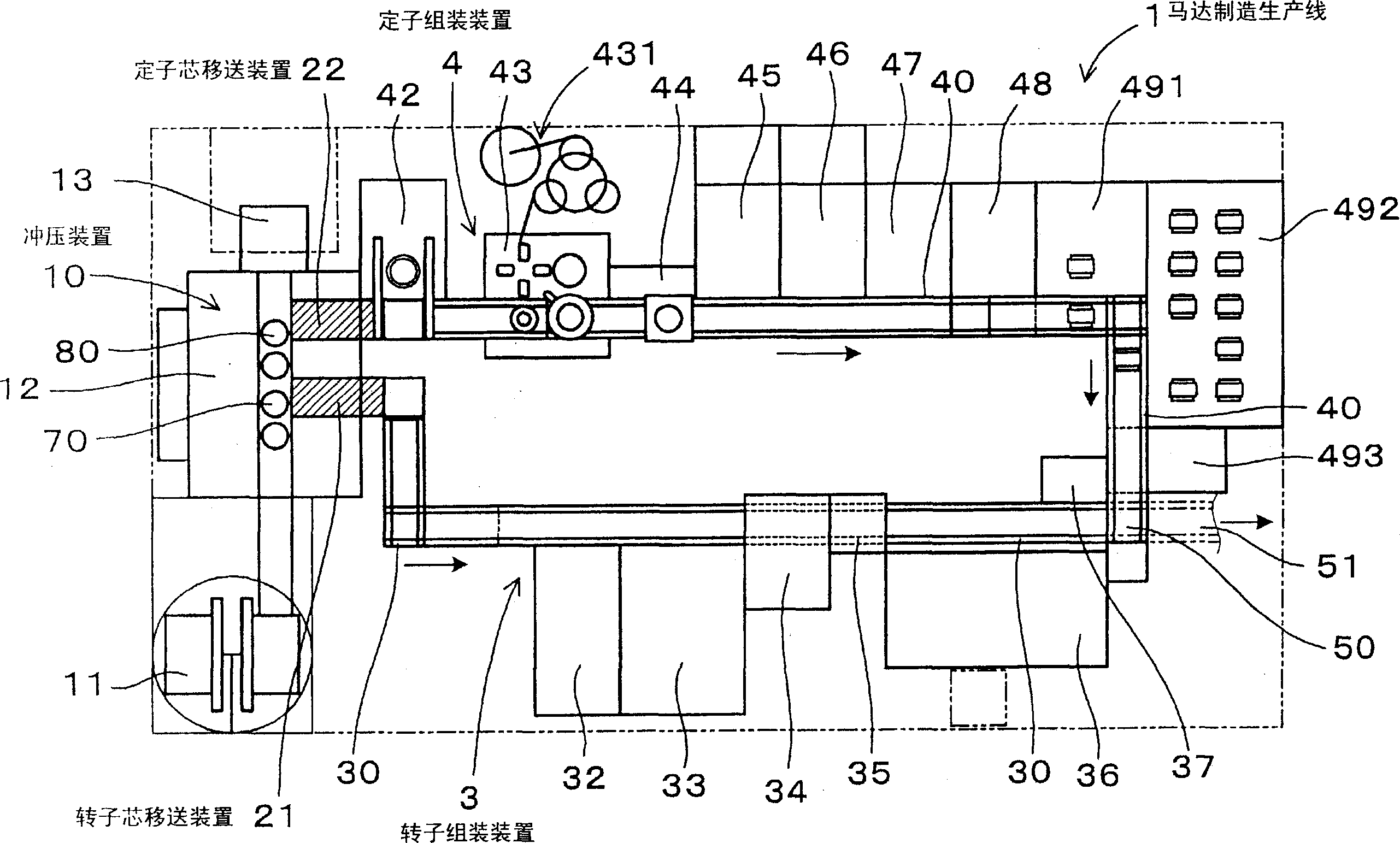
[0052] use Figure 1 to Figure 8 A motor manufacturing line related to an embodiment of the present invention will be described.

[0053] The motor manufacturing production line 1 of this example is as figure 1 Shown is a motor manufacturing line that simultaneously manufactures the rotor 7 ( FIG. 4 ) and the stator 8 ( FIG. 5 ) constituting the motor in parallel.

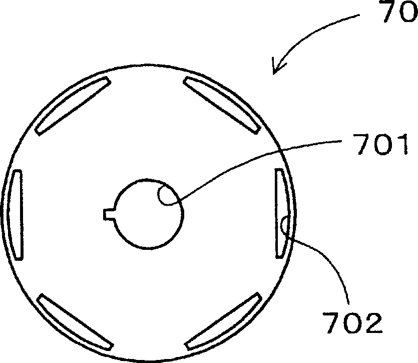
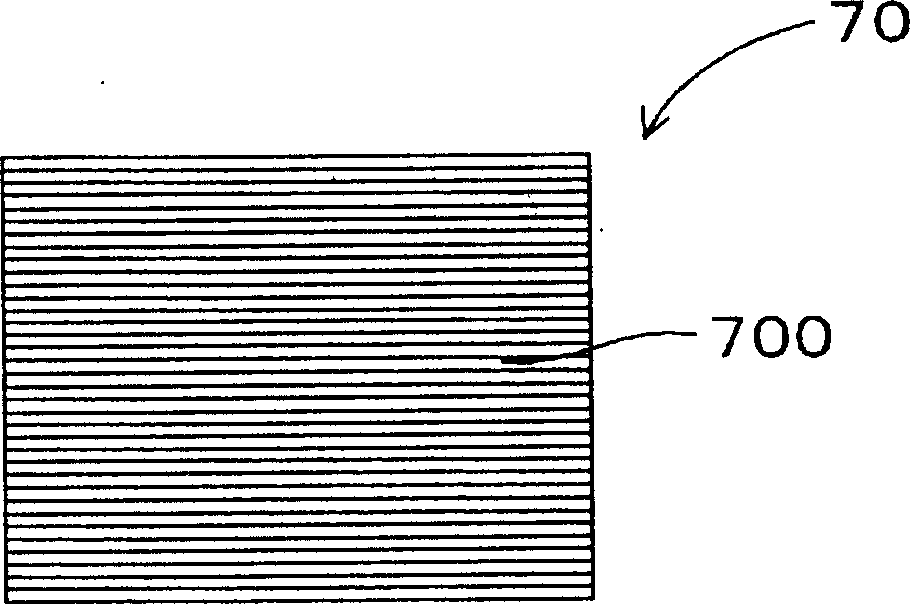
[0054] As shown in the figure, the motor manufacturing line 1 has a press device 10 that performs multiple presses while conveying a long steel plate, and laminates a plurality of steel plates to form a rotor core 70 ( FIG. 2 ) and a stator core 80 ( FIG. 3 ). The rotor assembly device 3 performs a plurality of manufacturing steps on the rotor core 70 to assemble the rotor 7 , and the stator assembly device 4 performs a plurality of manufacturing steps on the stator core 80 to assemble the stator 8 .

[0055] Between the rotor assembly device 3 and the press device 10 is provided a rotor core transfer device 21 ...


PUM


Abstract

A motor production line (1) which produces at least stators. It comprises a press device (10) which applies press working a plurality of times to a long-sized steel plate while conveying the latter, so as to form a stator core (80), and a stator assembling device (4) for assembling stators. Installed between the stator assembling device (4) and the press device (10) is a stator core transfer device (22) capable of successively transferring stator cores (80) formed in the press device (10) directly to the stator assembling device (4). It is preferable to install a rotor assembling device (3) for assembling rotors and a rotor core transfer device (21) capable of successively transferring rotor cores (70) formed in the press device (10) directly to the rotor assembling device (3).

Description

technical field [0001] The invention relates to a production line suitable for manufacturing motors with a small amount and many varieties and a control method thereof. Background technique [0002] When manufacturing a motor, the rotor and the stator that constitute the motor are manufactured separately, and finally these parts are combined to form a single motor. In addition, both the rotor and the stator use a rotor core and a stator core formed by laminating a plurality of electromagnetic steel sheets punched into a predetermined shape as iron cores. These rotor cores and stator cores are formed by a press device that performs a plurality of press processes while conveying a long electrical steel sheet. [0003] Such as Figure 9 As shown, in the conventional motor manufacturing line 9, in order to improve the production efficiency of rotor cores and stator cores, a dedicated stamping factory 91 equipped with a large stamping device can be used for mass production. The...

Claims


Application Information

Patent Timeline
Patent Type & Authority Applications(China)
IPC IPC(8): H02K15/02
CPCH02K15/02Y10T29/53148Y10T29/49009Y10T29/53143Y10T29/5141
Inventor 川崎睦之畔柳彻横山刚
Owner AISIN AW CO LTD
Why Eureka
Try Eureka