
Pipe clamping device

A technology in the pipe clamp and device, which is applied in the field of pipe clamp devices, can solve the problems of increasing the clamping force of the pipe, increasing the manufacturing cost, and the small force of the pipe clamping, and achieves the effect of strong clamping degree

Inactive Publication Date: 2006-03-22
郭炳运
View PDF0 Cites 9 Cited by
  • Summary
  • Abstract
  • Description
  • Claims
  • Application Information

AI Technical Summary

Problems solved by technology

Therefore, the shape of the pipe clamp device needs to be enlarged, and its manufacturing cost is therefore increased.
[0009] At the same time, because the conventional pipe clamping device only adopts one clamping ring, the clamping force to the pipe cannot be increased as expected
When designing the pipe clamp device, it is also impossible to reduce the outer diameter of the concave and convex hoops
As a result, its pipe holding power is not great
[0010] Moreover, because the conventional pipe clamp device has a gap space for elastic deformation after installation, part of the clamping force will be lost when elastic deformation occurs after installation, thus reducing the durability and reliability of product performance

Method used


Image

  • Pipe clamping device
  • Pipe clamping device
  • Pipe clamping device

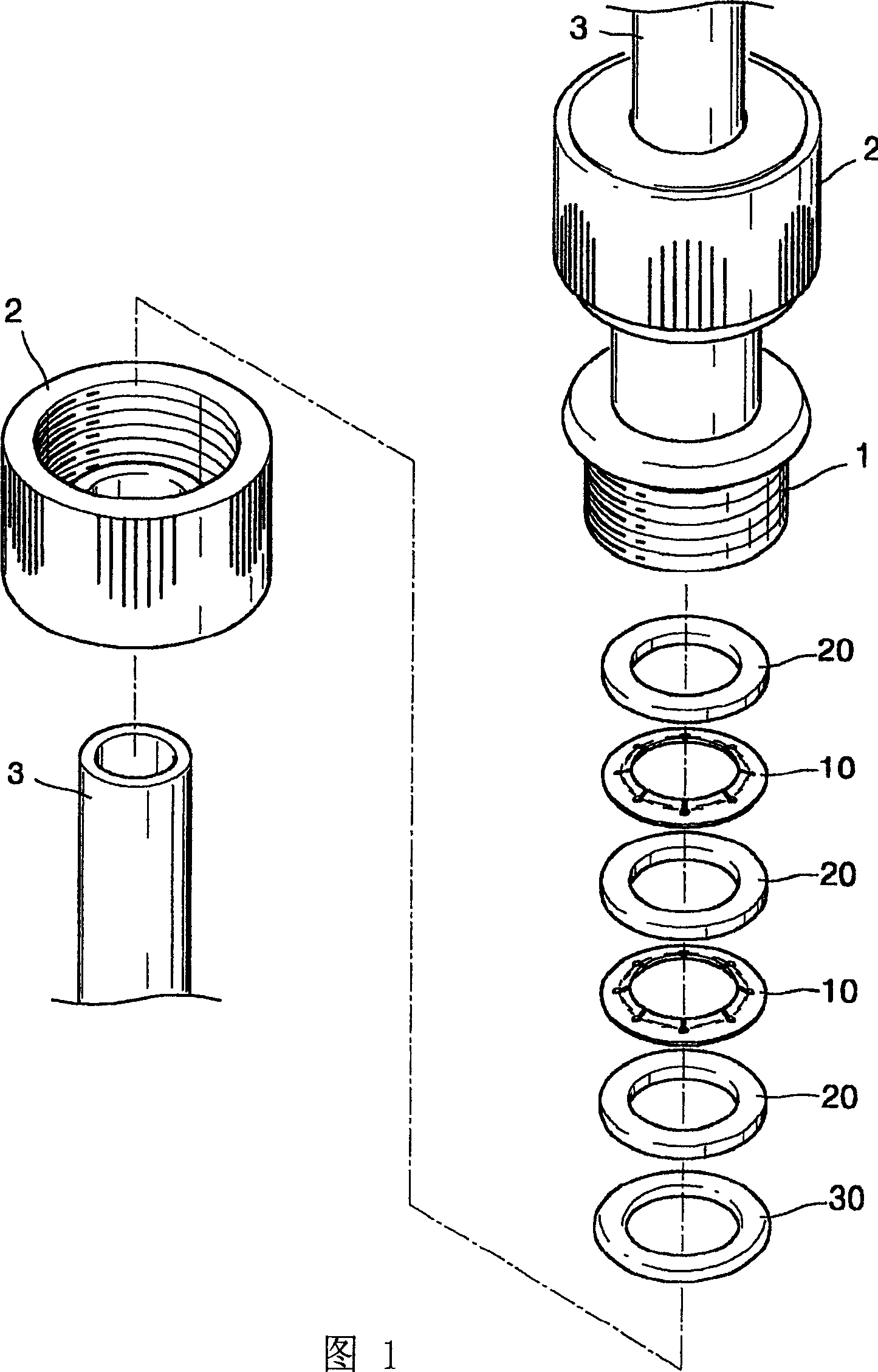
Examples


Embodiment Construction

[0027] A pipe clamp device according to a preferred embodiment of the invention will be described below with reference to the accompanying drawings.

[0028] First, as shown in Fig. 1, the pipe clamp device of the preferred embodiment of the invention is installed between a female hoop 1 and a male hoop 2 to clamp a pipe 3, wherein the female hoop and the male hoop are used in pairs. The pipe clamp device includes a clamping ring 10, which is used to compress the pipeline 3, a pressure ring 20, which provides pressure to the clamping ring 10 to make the gap of the clamping ring 10 smaller, and a sealing ring 30, For sealing pipes3.

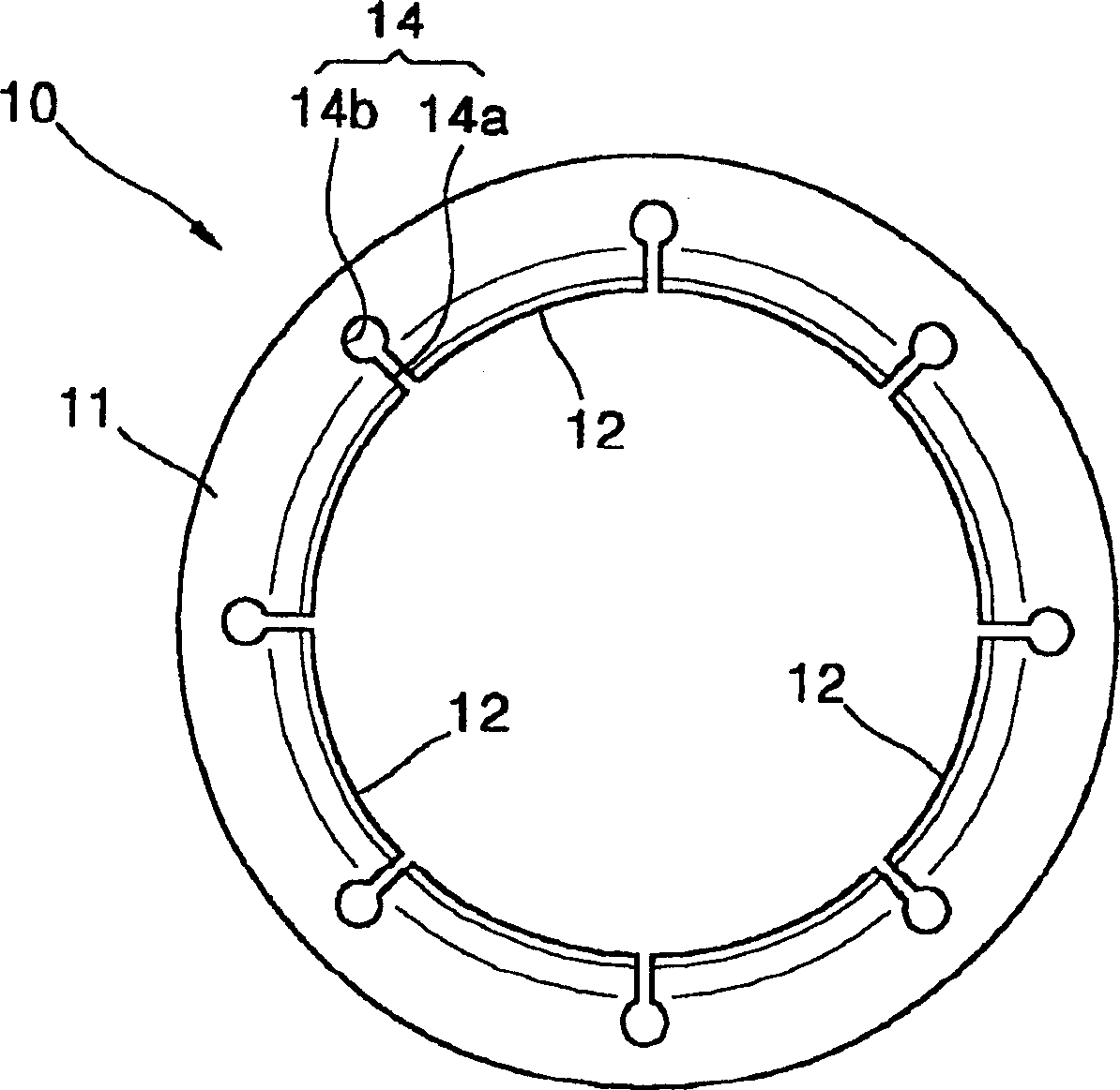
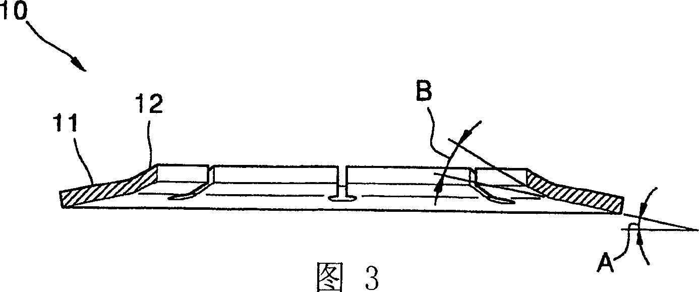
[0029] That is, if figure 2 As shown, the clamping ring 10 is installed between the concave hoop 1 and the convex hoop 2, and the clamping edge 12 is used to clamp the outer circumference of the pipeline 3 and fix the pipeline 3, and the clamping edge is located on the inner circumference of the clamping ring 10 , made of elastic material, can b...


PUM


Abstract

A wireless Internet phone is provided to offer mobility through a wireless LAN-based VoIP service by installing a base machine to implement a base station function and a handset to execute phone calls through the Internet. A wireless Internet phone consists of a handset(1), a base machine(2), and an Internet phone base station(3). The handset(1), communicating data with the base machine(2) by wireless, connects a user to the other side through the Internet. The base machine(2), if packet data containing a phone number and ID information are received from the handset(1), transmits the packet data to the Internet phone base station(3) through the Internet. The Internet phone base station(3), if the packet data are received from the base machine(2), executes authentication for the user of the handset(1) by using the ID contained in the packet data. As a result of authentication, in case that it is judged that the user of the handset(1) is a service subscriber, the Internet phone base station(3) makes a call to the phone number contained in the packet data.

Description

technical field [0001] The invention relates to a pipe clamping device, in particular to a pipe clamping device which generates greater clamping force through the elastic deformation of the clamping ring when the bolt is tightened. Background technique [0002] Usually, a clamping device is widely used when connecting a pipeline to another pipeline. This clamping device firmly clamps and fixes the pipelines to connect the two pipelines to prevent liquid leakage in the pipelines. [0003] A conventional pipe clamp device includes a clamping ring, which is located between a concave hoop and a convex hoop, and the two hoops are fastened by bolts; and the clamping ring is in the shape of a metal ring, and the clamping ring The clamping edge clamps the outer circumference of the pipeline to prevent the pipeline from coming out; and a sealing ring seals the gap between the clamped pipelines. [0004] Here, the clamping ring is pressed against the pipeline by strong force, and the...

Claims


Application Information

Patent Timeline
Patent Type & Authority Applications(China)
IPC IPC(8): F16L19/00F16L19/08F16L37/091
CPCF16L19/086F16L37/091F16L19/08
Inventor 郭炳运
Owner 郭炳运
Learn More