Magnetic field sensor and electrical current sensor therewith

A technology of magnetic field sensor and current sensor, applied in voltage/current isolation, size/direction of magnetic field, magnetic field measurement using the principle of magnetic flux control, etc., which can solve the problems of Hall unit stability and linear operation

Active Publication Date: 2006-03-22
莱姆电子(中国)有限公司
View PDF0 Cites 39 Cited by
  • Summary
  • Abstract
  • Description
  • Claims
  • Application Information

AI Technical Summary

Problems solved by technology

Temperatures in the 120°C range are common when operating in IPM, which is problematic for stable and linear operation of Hall cells without bias drift

Method used


Image

  • Magnetic field sensor and electrical current sensor therewith
  • Magnetic field sensor and electrical current sensor therewith
  • Magnetic field sensor and electrical current sensor therewith

Examples


Embodiment Construction

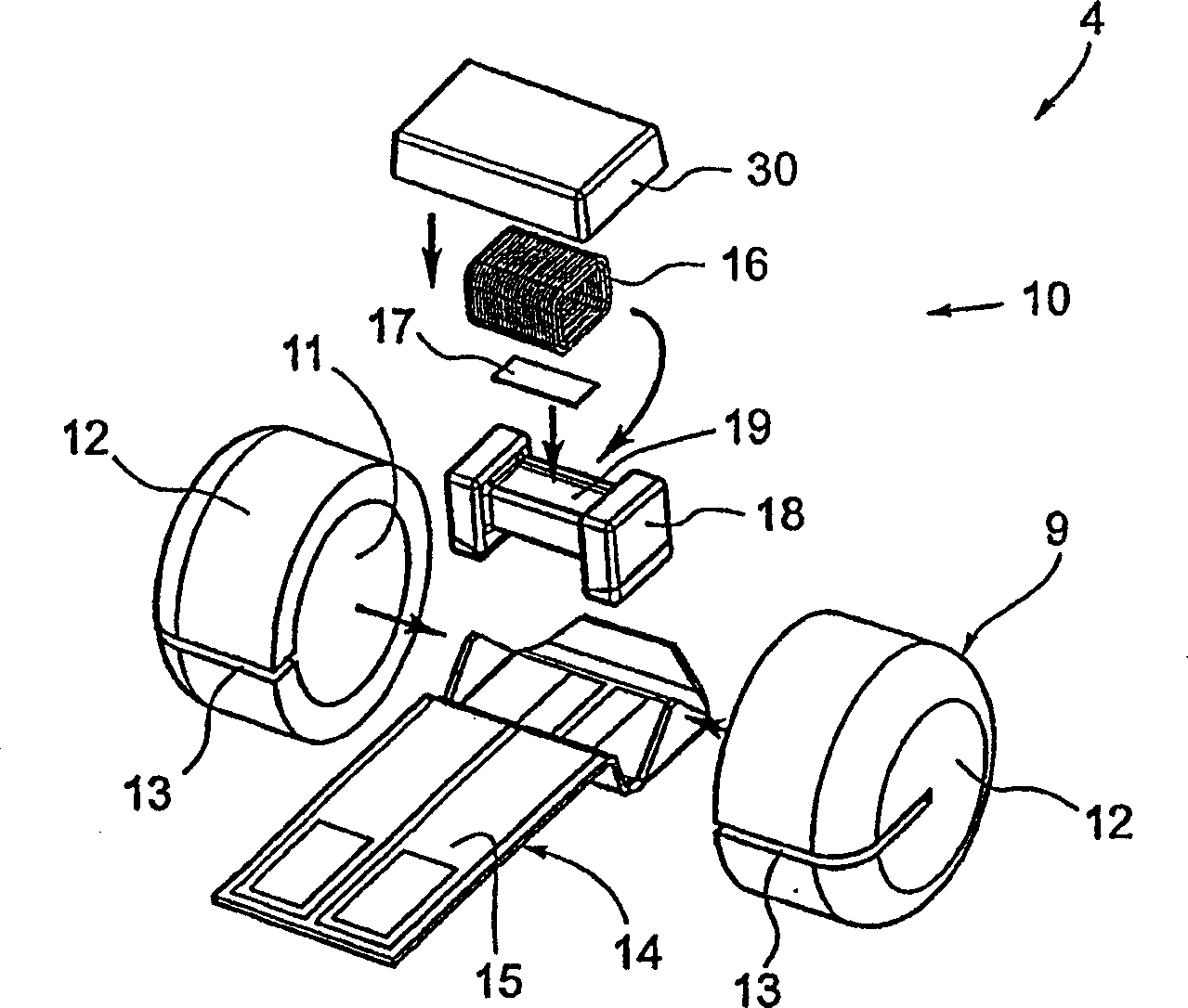
[0028] Referring to the drawings, the current sensor 2 for measuring the primary current Ip in the primary conductor 1 includes a magnetic circuit 3 and a magnetic field sensor 4 , 104 , 204 , 304 , 404 . The magnetic circuit 3 comprises a magnetic core 5 of magnetically permeable material and is provided between the end faces 27a, 27b with an air gap 6 in which the magnetic field sensor is placed. The magnetic core 5 is generally shown as an annular part with a central opening 7 through which the primary conductor 1 extends. However, other magnetic circuit shapes may also be provided, such as rectangular, polygonal, toroidal or other shapes, without departing from the scope of the present invention. Furthermore, the primary conductor 1 is shown extending through the magnetic circuit, however, the primary magnet may also be provided with a plurality of windings or conductor parts wound around the magnetic circuit core 5 and extending through the opening 7 . The magnetic mater...


PUM


Abstract

A magnetic field sensor comprises a magnetic field sensing cell (10) and a magnetic shield (9) comprising at least two parts (12a, 12b) separated by an air-gap (20) and surrounding the magnetic field sensing cell positioned in a cavity (11) of the magnetic shield.

Description

technical field [0001] The invention relates to a magnetic field sensor for measuring magnetic induction (magnetic flux density). The invention also relates to a current sensor for measuring a current flowing in a conductor by sensing a magnetic field generated by the conductor. Background technique [0002] Many conventional current sensors have a magnetic circuit comprising a core of magnetic material provided with an air gap in which a magnetic field sensor, such as a Hall effect sensor, is placed. The conductor in which the current to be measured flows, often called the "primary conductor", passes through the magnetic circuit once or several times. These sensors are typically found in applications where relatively large currents are measured, or where simple devices such as current bypasses or transformers cannot be used for reasons such as the need for galvanic isolation or the presence of a DC component in the current being measured . [0003] Current sensors of the...

Claims


Application Information

Patent Timeline
Patent Type & Authority Applications(China)
IPC IPC(8): G01R33/04G01R15/20
CPCG01R15/202G01R33/04G01R15/185G01R15/207
Inventor 沃尔夫兰姆·特潘
Owner 莱姆电子(中国)有限公司
Why Eureka
Try Eureka