Pneuamtic gate of bowling game equipment

A device and bowling technology, applied in bowling balls, sports accessories, etc., can solve the problems of not being able to start in time, only releasing the bottle from the goal gate by mistake, and releasing the goal gate.

Active Publication Date: 2006-03-29
何帮喜
View PDF2 Cites 6 Cited by
  • Summary
  • Abstract
  • Description
  • Claims
  • Application Information

AI Technical Summary

Problems solved by technology

[0002] There are three kinds of bowling gates in the prior art: a kind of is to belong to the part in the bowling ball (hereinafter referred to as ball) automatic ball return device, promptly a dial is set outside the ball gate, in operation, keeps beating left and right, generally controls two pins at the same time. When the ball is returned to the adjacent fairway, when the dial is shot to the left, the ball blocking the left fairway will not go out, while the ball on the right fairway will go out, and vice versa. The disadvantage is that: when the balls in two adjacent fairways are almost going out , the plectrum must be repeatedly tapped left and right several times in order to use the time difference to release one of the balls out of its corresponding goal gate, and then release the other ball out of its corresponding goal gate. Put the bottle out of the goal; another Chinese patent ZL98204485.2 discloses a purely mech

Method used


Image

  • Pneuamtic gate of bowling game equipment
  • Pneuamtic gate of bowling game equipment
  • Pneuamtic gate of bowling game equipment

Examples


Embodiment Construction

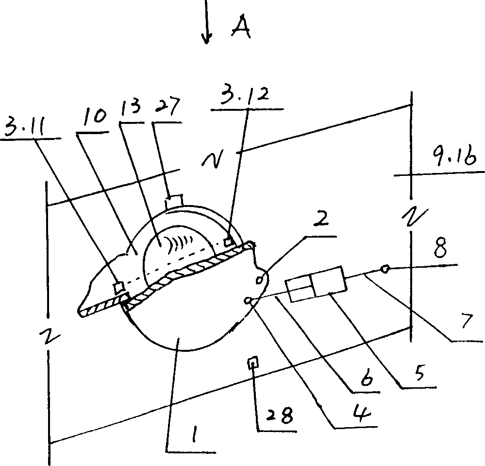
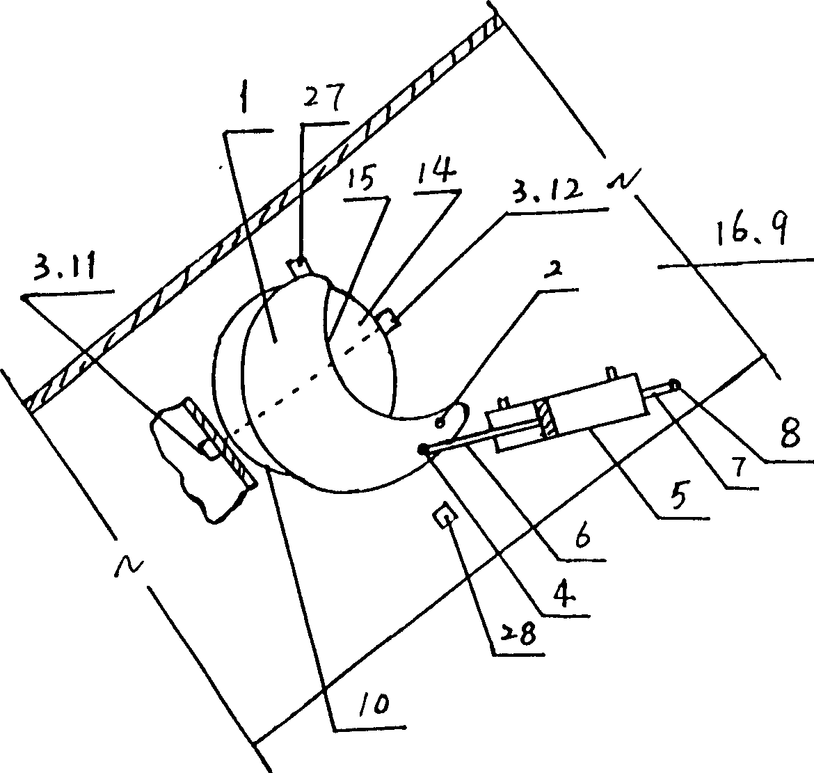
[0012] Describe in detail in conjunction with the accompanying drawings;

[0013] As shown in Figure 1, the switch control mechanism 3 is an optical switch, and its transmitter 11 and receiver 12 are all installed on the inside of the goal 10, or as shown in Figure 2, the transmitter 11 and receiver 12 of the optical switch Be contained in the inside and outside of goal gate 10 respectively, or anti-position installation, at this moment, goal plate 1 must have the concave arc 15 that can form gap 14 between the edge line of goal gate 10 when being in the closed position shape, and It can ensure that the light signal of the light control switch can pass through the gap 14 reliably, and the bottle cannot pass through the gap 14 .

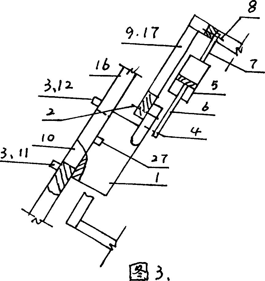
[0014] As shown in Figures 1 and 3, the door frame 9 is a wall panel 16 or an independent frame 17 of the ball accelerator, that is, the goal plate 1 and the cylinder 5 are all mounted on the independent frame 17 of the ball accelerator.

[0015] As ...


PUM


Abstract

A pneumatic gate unit of bowling apparatus is composed of a gate board able to be turned up and down around its horizontal rotary axle, a cylinder with a piston rod pivoted via pin to said gate board, a frame or wall for supporting the gate board, an optically (or magnetically) controlled open-close controller, and relative pneumatic and electric control systems. Its advantage is high speed to open or close gate.

Description

technical field [0001] The invention belongs to the field of cultural and sports facilities, and relates to a pneumatic goal in bowling equipment. Background technique [0002] There are three kinds of bowling gates in the prior art: a kind of is to belong to the part in the bowling ball (hereinafter referred to as ball) automatic ball return device, promptly is provided with a dial outside the ball gate, in operation, keeps beating left and right, generally controls two pins at the same time. When the ball is returned to the adjacent fairway, when the puck is shot to the left, the ball blocking the left fairway will not go out, while the ball on the right fairway will go out, and vice versa. The disadvantage is: when the balls in two adjacent fairways are almost going out , the plectrum must be repeatedly tapped left and right several times in order to use the time difference to release one of the balls out of its corresponding goal gate, and then release the other ball out...

Claims


Application Information

Patent Timeline
IPC IPC(8): A63D5/02
Inventor 何帮喜
Owner 何帮喜
Why Eureka
Try Eureka