Method for producing mixed electrolyzed water

A manufacturing method, electrolyzed water technology, applied in the direction of water treatment parameter control, chemical instruments and methods, electrochemical water/sewage treatment, etc., can solve the problems of inability to electrolyze additives, reduction ability reduction, use, etc., and achieve high safety , Improve the disproportionation ability, the effect of simple manufacturing equipment

Inactive Publication Date: 2006-03-29
MIKUNI CORP +1
View PDF1 Cites 4 Cited by
  • Summary
  • Abstract
  • Description
  • Claims
  • Application Information

AI Technical Summary

Problems solved by technology

In the basic range, the OH group at the 2 position dissociates or -O - and H + , but due to the low degree of dissociation of these, it cannot be used as an electrolytic aid
In addition, the electrolysis process in the electrolysis of an aqueous solution of ascorbic acid is complicated, and intermediate products were not identified, but it was basically observed as a redox reaction
[0007] It is also well known that ascorbic acid itself acts as a strong reducing agent, but it causes autooxidation by itself in aqueous solution, reducing the reducing ability

Method used


Image

  • Method for producing mixed electrolyzed water
  • Method for producing mixed electrolyzed water
  • Method for producing mixed electrolyzed water

Examples


preparation example Construction

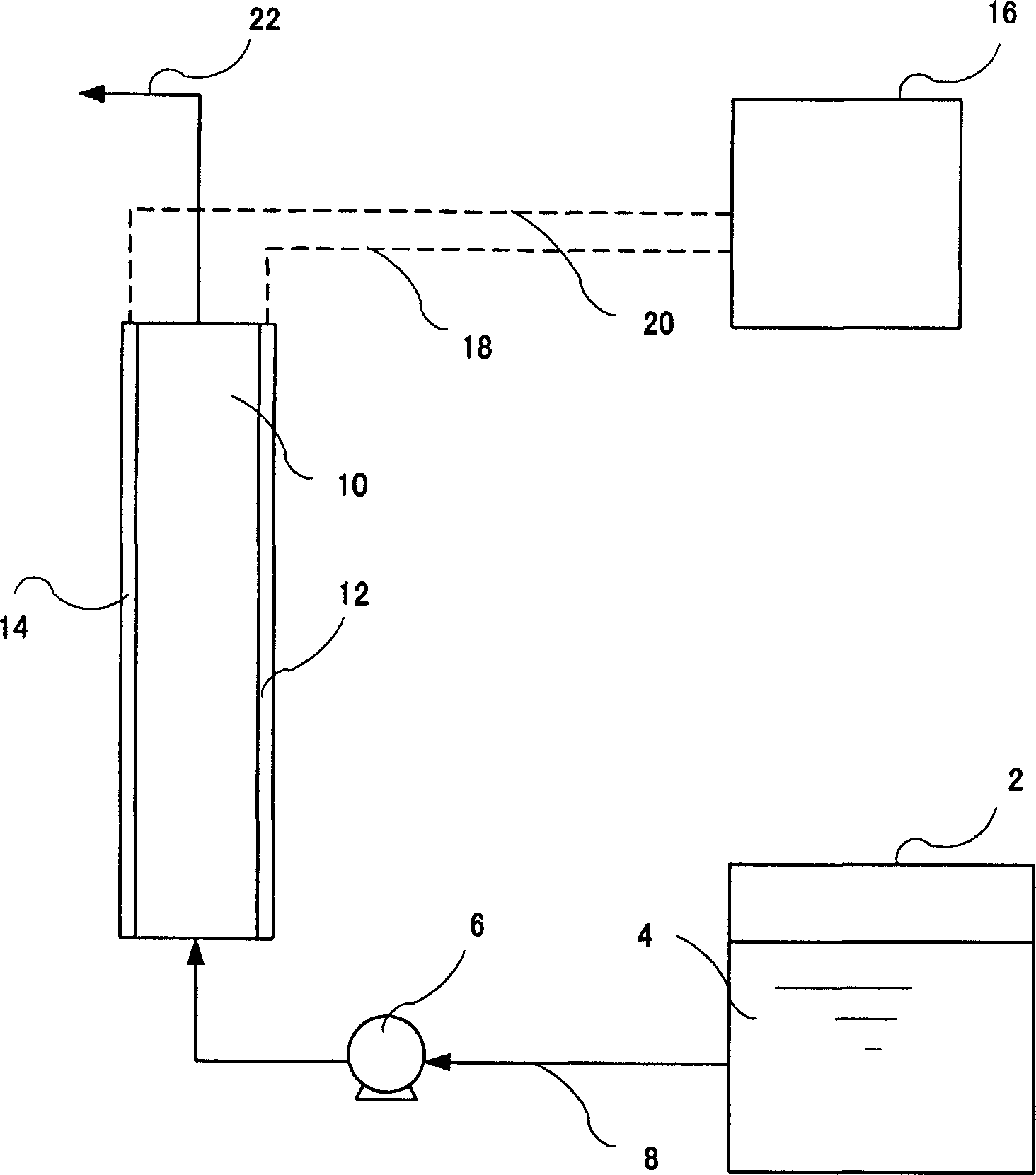
[0066] A method for preparing such an aqueous organic electrolyte solution 4 includes a method of dissolving an organic electrolyte such as ascorbic acid in purified water (pure water) such as distilled water or deionized water within the above-mentioned concentration range.

[0067] 6 is a pump attached to the organic electrolyte aqueous solution supply pipe 8 , and by operating the pump 6 , the organic electrolyte aqueous solution 4 is sent to the diaphragmless electrolytic cell 10 through the supply pipe 8 .

[0068] The aforementioned diaphragmless electrolytic cell 10 has a pair of electrodes 12, 14 opposed to each other at a predetermined interval inside. The distance between the aforementioned pair of electrodes 12 and 14 is 2 mm or less, preferably 1.5-0.05 mm, more preferably 1.0-0.1 mm. When the distance between the electrodes exceeds 2 mm, the anode-side electrolyzed water generated by electrolysis and the cathode-side electrolyzed water are not sufficiently mixed, ...

Embodiment 1

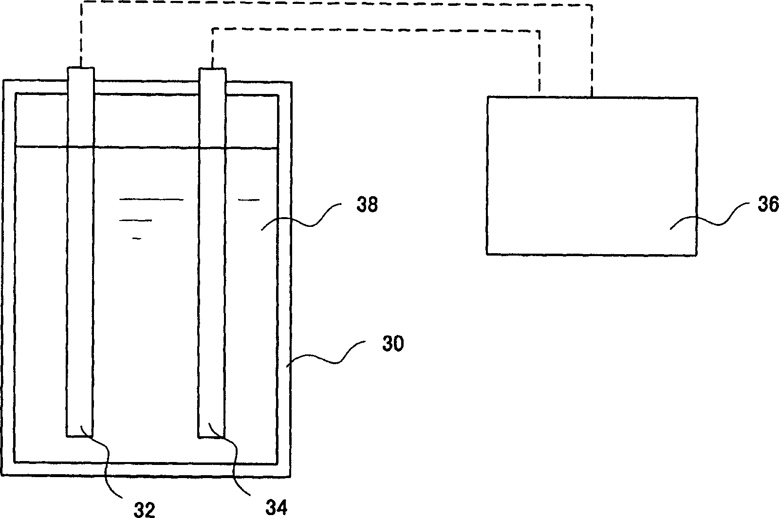
[0080] use figure 2 The electrolysis device shown in , electrolyzes electrolyzed raw water containing ascorbic acid (AsA).

[0081]A pair of 10 x 10 cm titanium coated with platinum electrodes was installed in the electrolytic cell. The distance between electrodes was 2mm. The electrolytic cell is a rectangle with a length of 11 cm, a width of 5 cm, and a height of 12 cm. An AsA aqueous solution with a concentration of 30 mM was prepared, and 660 ml of the AsA aqueous solution was filled in the aforementioned electrolytic cell. While stirring the AsA aqueous solution, conduct electrolysis by passing a current of 0.25A to the two electrodes. Electrolysis was performed by changing the polarity every 30 seconds from the start of electrolysis. Table 1 shows the pH, oxidation-reduction potential (ORP), dissolved oxygen (DO), and electrical conductivity (EC) of the mixed electrolyzed water produced by electrolysis. In addition, the mixed electrolyzed water produced by electrol...


PUM


Abstract

A method for producing a mixed electrolyzed water composed of a cathode side electrolyzed water and an anode side electrolyzed water, characterized in that electrolysis is effected while an aqueous organic electrolyte solution containing less than 0.1 mM of an aqueous inorganic salt and 1 to 50 mM of an organic electrolyte is fed to a non-diaphragm electrolytic vessel having at least one pair of inactive electrodes with a distance between the electrodes of 2 mm or less, wherein when the above aqueous organic electrolyte solution adjusted to have a same pH as that of said mixed electrolyzed water formed by electrolysis is subjected to neutralization titration with an aqueous sodium hydroxide solution, the amount of neutralization titration is less than that in the case of the original aqueous solution or the resultant solution exhibits higher capability per mole for the disproportionation of a superoxide radical.

Description

technical field [0001] The invention relates to a method for producing mixed electrolyzed water with superoxide free radical disproportionation, anode side electrolyzed water and cathode side electrolyzed water. More specifically, it relates to a method for producing mixed electrolyzed water having disproportionation of superoxide radicals, etc., by electrolyzing an aqueous organic electrolyte solution containing only an organic water-soluble electrolyte such as ascorbic acid as an electrolyte. Background technique [0002] It is well known that a dilute electrolyte aqueous solution of alkali metal chloride is electrolyzed through a diaphragm using an electrolytic cell equipped with an inert electrode composed of platinum or a platinum alloy, and the anode-side electrolyzed water (acidic water) with a low pH generated by electrolysis on the anode side is taken out, and the The electrolyzed water is used for sterilization or disinfection technology. As the separator, a charg...

Claims


Application Information

Patent Timeline
Patent Type & Authority Applications(China)
IPC IPC(8): C02F1/461C02F1/467C02F1/46
CPCC02F1/46109C02F2209/04C02F2201/4618C02F2103/026C02F2209/06C02F1/4672C02F2209/22C02F2209/05C02F2303/04C02F1/461C02F1/467
Inventor 花冈孝吉
Owner MIKUNI CORP
Why Eureka
Try Eureka