Multiphase motor voltage control for phase windings of different wire gauges and winding turns

A multi-phase motor, motor control technology, applied in different voltage fields

Inactive Publication Date: 2006-03-29
WAVECREST LAB LLC
View PDF4 Cites 1 Cited by
  • Summary
  • Abstract
  • Description
  • Claims
  • Application Information

AI Technical Summary

Problems solved by technology

[0013] Although this setup broadens the speed range over which high efficiency is obtained, the inductive nature of the motor windings requires precise timing control of the connection or disconnection of the taps to the supply

Method used


Image

  • Multiphase motor voltage control for phase windings of different wire gauges and winding turns
  • Multiphase motor voltage control for phase windings of different wire gauges and winding turns
  • Multiphase motor voltage control for phase windings of different wire gauges and winding turns

Examples


Embodiment Construction

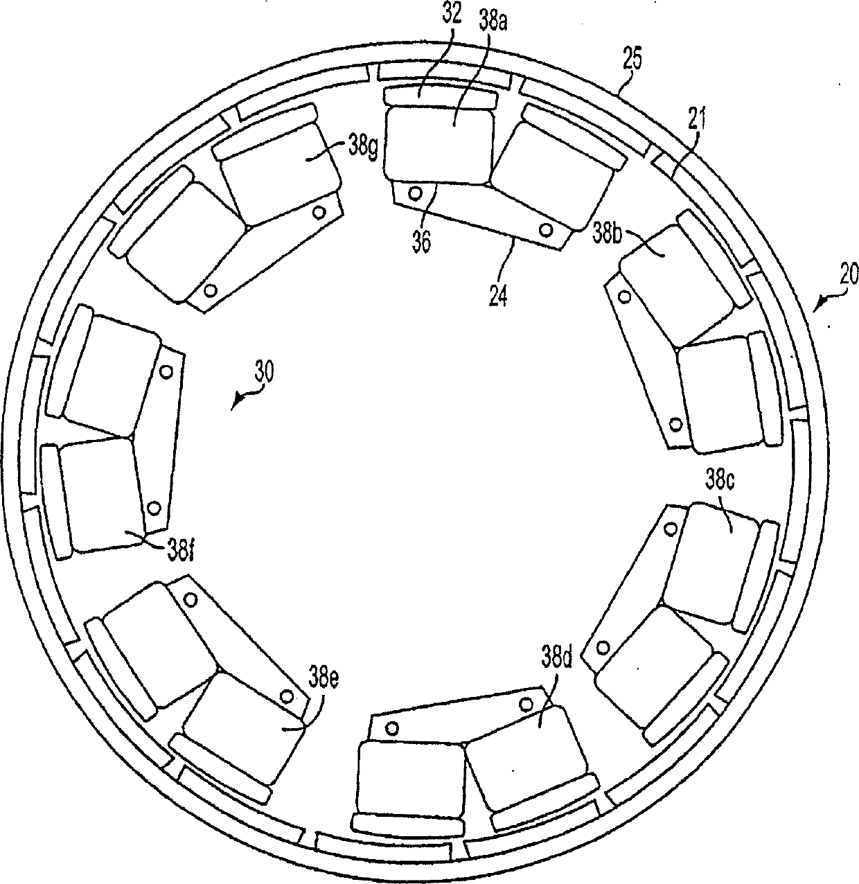
[0029] Figure 2 is a schematic structure of rotor and stator elements used in the present invention. The motors listed herein are described in more detail with reference to the aforementioned copending Maslov et al. application 09 / 826422. The rotor member 20 is an annular structure with permanent magnets 21 spaced apart from each other and distributed generally uniformly along the circumferential support plate 25 . The permanent magnets are rotor poles whose magnetic polarities alternate along the inner circumference of the ring hole. The rotor surrounds the stator member 30, the rotor and stator member being spaced apart by an annular radial air gap. The stator 30 includes a plurality of electromagnet core segments of uniform structure, which are evenly distributed along the air gap.

[0030] The stator comprises seven core segments, each formed as a common U-shaped magnetic structure 36 comprising two poles having a surface 32 facing the air gap. Windings 38 are wound aro...


PUM


Abstract

A multiphase motor has a plurality of ferromagnetically isolated stator electromagnets distributed about an axis of rotation. Successive ranges of speed during which the motor can be expected to operate are defined. A specific subset of the electromagnets is associated for each speed range, each specific subset comprising a different combination of electromagnets. Respective voltage magnitudes to be applied to each phase winding for each defined speed range are predefined. The motor speed is sensed throughout motor operation. In each defined speed range, only the electromagnets of the associated subset are energized, each of the energized electromagnets having applied thereto a different predefined voltage magnitude.

Description

[0001] Related applications [0002] The present application contains subject matter related to the following copending U.S. Application Nos.: 09 / 826423 filed Apr. 5, 2001 by Boris Maslov et al. 09 / 826422, filed June 19, 2002, 10 / 173610, Boris Maslov et al., 10 / 290505, Nov. 8, 2002, and Alexander Gladkov, 1, 2003 10 / 352897 filed on the 9th. Generally, these pending application numbers all belong to this application. The disclosures of these applications are incorporated herein by reference. technical field [0003] The present invention relates to the control of multiphase electric machines, and in particular to the application of different voltages to individual phase windings of different winding and coil size topologies over the entire operating speed range of the continuous electric machine. Background technique [0004] Improvements in electronic systems such as microcontrollers, microprocessors, and the availability of improved portable power sources for motor contr...

Claims


Application Information

Patent Timeline
Patent Type & Authority Applications(China)
IPC IPC(8): H02P6/00H02P6/08H02K3/28H02K21/22
CPCH02K3/28H02K21/225H02K1/187H02K1/2733
Inventor 亚历山大·A·格拉德科夫
Owner WAVECREST LAB LLC
Why Eureka
Try Eureka