Resonance drive actuator

一种致动器、电磁驱动的技术,应用在电气元件、机电装置等方向,达到容易共振、减小长度的效果

Inactive Publication Date: 2006-04-05
MABUCHI MOTOR
View PDF1 Cites 9 Cited by
  • Summary
  • Abstract
  • Description
  • Claims
  • Application Information

AI Technical Summary

Problems solved by technology

In other words, without Figure 9 The flat spring shown in is designed for applications where the movable segment reciprocates in a circumferential direction

Method used


Image

  • Resonance drive actuator
  • Resonance drive actuator
  • Resonance drive actuator

Examples


Embodiment Construction

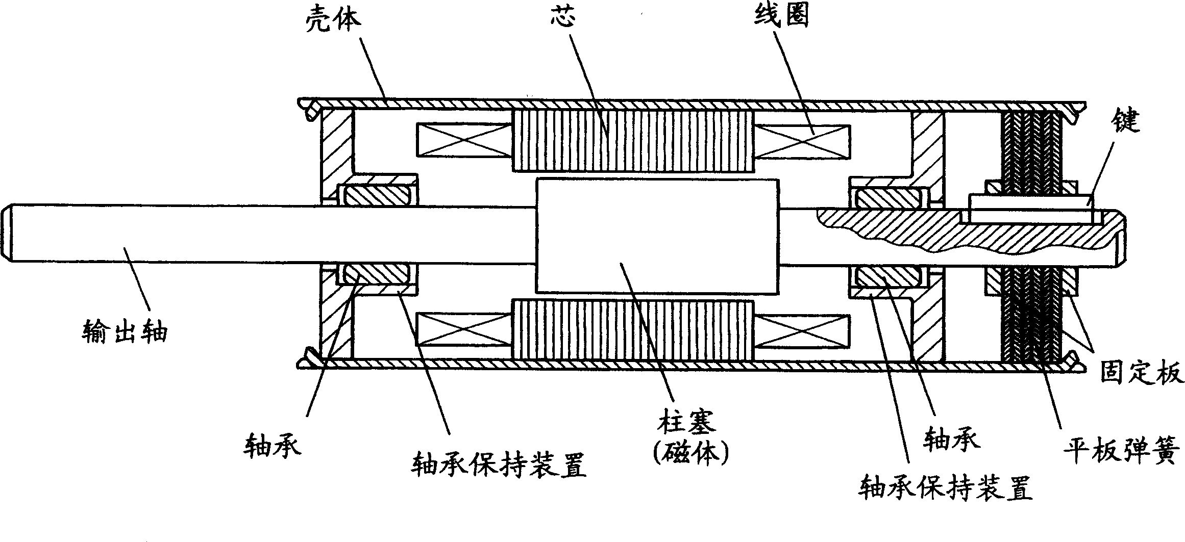
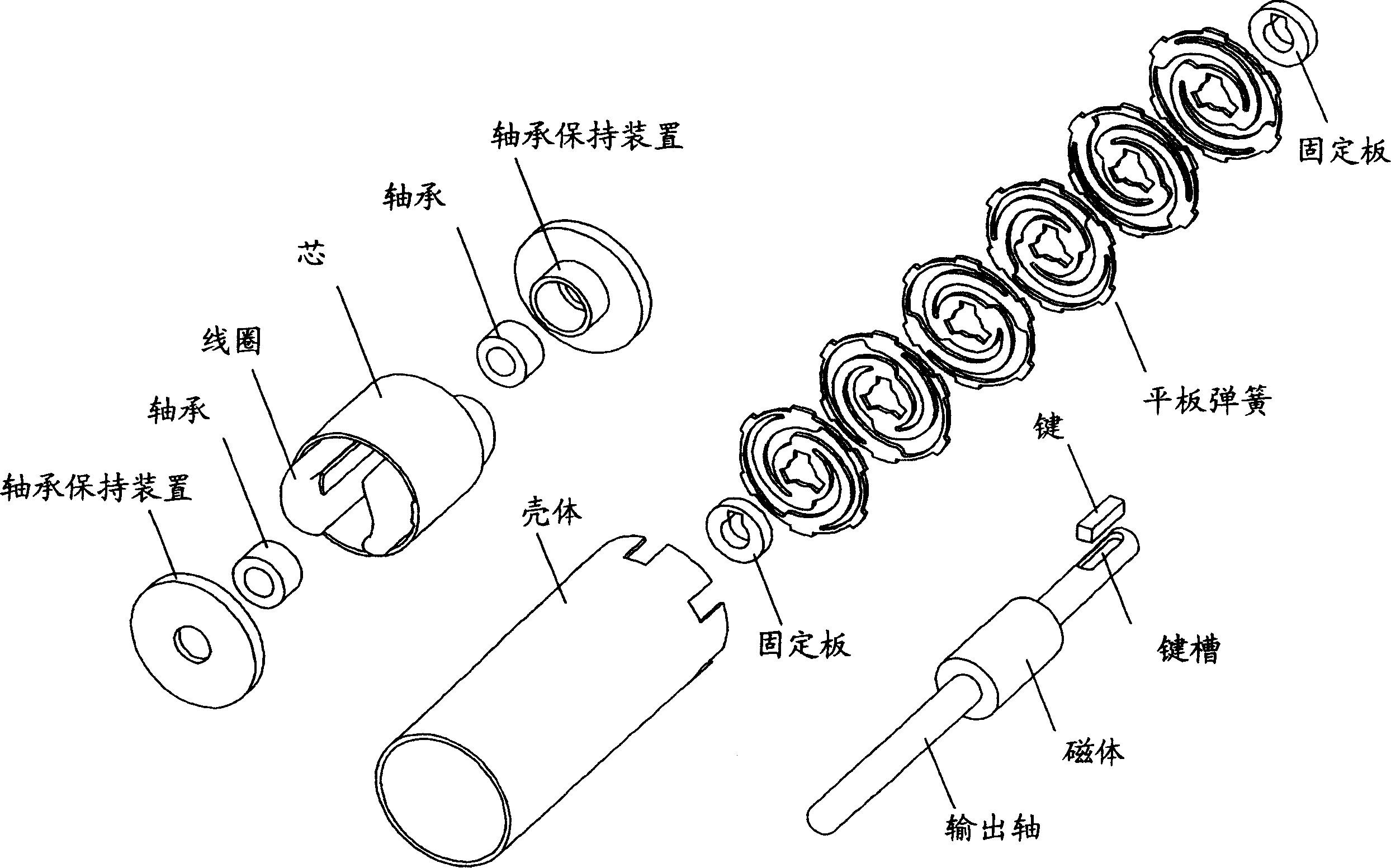
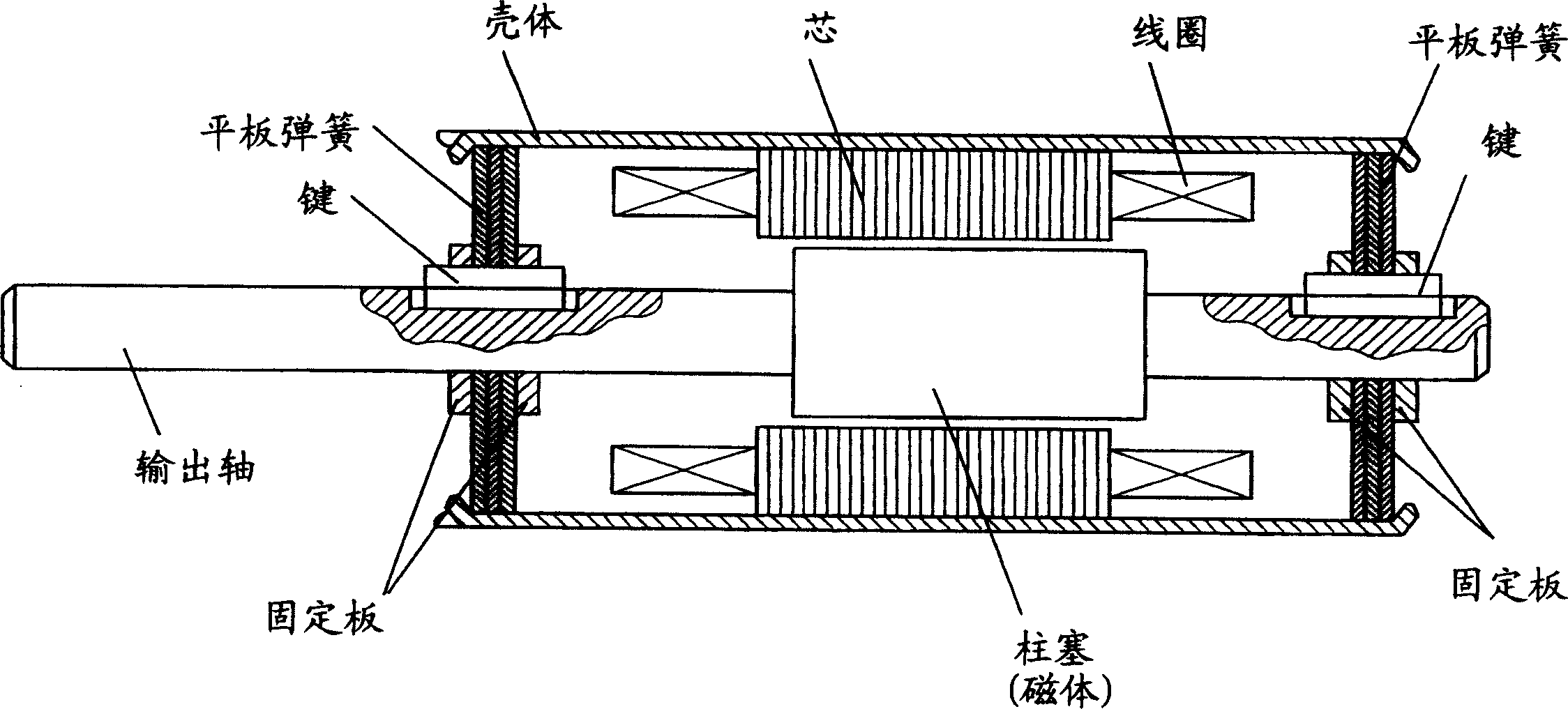
[0027] Embodiments of the present invention will be described in detail below with reference to the drawings. figure 1 is a sectional view showing a first embodiment of the actuator according to the invention. figure 2 for figure 1 An exploded perspective view of the actuator. as in figure 1 and 2 As shown in , a movable section of the actuator includes an output shaft that outputs a driving force and a cylindrical plunger fixed to the output shaft, the plunger is made of a magnet to move along the The magnets are magnetized in a circumferentially spaced manner. A load (not shown) is connected to one end of the output shaft, and the load is resonantly driven at an axial resonant frequency and a circumferential resonant frequency, the axial resonant frequency being determined by the spring force of a spring member and a movable section The mass of , while the circular resonance frequency is determined by the spring force and the inertia of the movable section. For exa...


PUM


Abstract

A resonance drive actuator includes a casing; an electromagnetic drive section supported in the interior of the casing; a plunger to be reciprocatively driven at least in a rotational direction or in an axial direction by the electromagnetic drive section; an output shaft on which the plunger is fixed; and a spring which acts between the output shaft and the casing. The actuator resonantly drives a load connected to an end of the output shaft. The spring is a plate spring which integrally includes a casing inner-surface abutment portion fixedly abutting the inner surface of the casing, an output-shaft abutment portion fixedly abutting an outer surface of the output shaft, and a connection portion having the form of a strip and connecting the output-shaft abutment portion and the casing inner-surface abutment portion. The plate spring is fixed to both of the inner surface of the casing, and the output shaft.

Description

technical field [0001] The present invention relates to a resonantly driven actuator, which reciprocally drives an output shaft, to which a load is connected, by means of an electromagnetic drive force, and drives the output shaft in motion at least in the axial direction at an axial resonant frequency, wherein The axial resonant frequency is determined by the spring force of a spring element and the mass of a movable section, or the output shaft is driven to move at a circular resonant frequency in the direction of rotation, which is determined by the spring force and the movable part. The inertia of the partial segment is determined. Background technique [0002] The actuator, which can be used as a driving section of an electric shaver or an electric toothbrush, reciprocates a movable section in an axial direction and in a rotational direction by means of an electromagnetic driving force. At this time, the movable section produces reciprocating motion at an axial resonan...

Claims


Application Information

Patent Timeline
Patent Type & Authority Applications(China)
IPC IPC(8): H02K33/18
CPCH02K33/16
Inventor 荻野久史梅村聪彦筱崎康明
Owner MABUCHI MOTOR
Why Eureka
Try Eureka