Injection molding machine driving device, injection device and mold clamping device

A technology of injection molding machine and driving device, applied in the field of driving device, can solve the problems of increasing the linear motor, increasing the cost of the driving device, increasing the weight of the mover, etc. Effect of Moment of Inertia

Inactive Publication Date: 2006-04-05
SUMITOMO HEAVY IND LTD
View PDF0 Cites 16 Cited by
  • Summary
  • Abstract
  • Description
  • Claims
  • Application Information

AI Technical Summary

Problems solved by technology

[0015] However, if a linear motor is used in the drive device of the prior art described above, since the linear motor does not have a speed reduction mechanism, when the linear motor is installed as a drive device in an injection molding machine, which is a mechanical device with a high load, , if you want to generate a large thrust or drive continuously with a short cycle, it is necessary to increase the power of the linear motor
[0016] Therefore, in order to enlarge the capacity of the linear motor, it is only necessary to enlarge the area of ​​the permanent magnet used in the linear motor, but since the shape of the linear motor is generally flat, if the area of ​​the permanent magnet is enlarged, not only the linear motor will become larger , the driving device is correspondingly enlarged, and the cost of the driving device is correspondingly high
In addition, the weight of the mover also increases corresponding to the increase in the area of ​​the permanent magnet, and the high speed and corresponding characteristics of the driving device cannot be sufficiently improved.
[0017] In addition, when a linear motor is used in the injection device, since the linear motor for injection and the motor for metering are arranged adjacent to each other on the same straight line, the size of the output device in the axial direction becomes larger and the size increases accordingly. up

Method used


Image

  • Injection molding machine driving device, injection device and mold clamping device
  • Injection molding machine driving device, injection device and mold clamping device
  • Injection molding machine driving device, injection device and mold clamping device

Examples


Embodiment Construction

[0042] Embodiments of the present invention will be described in detail below with reference to the drawings.

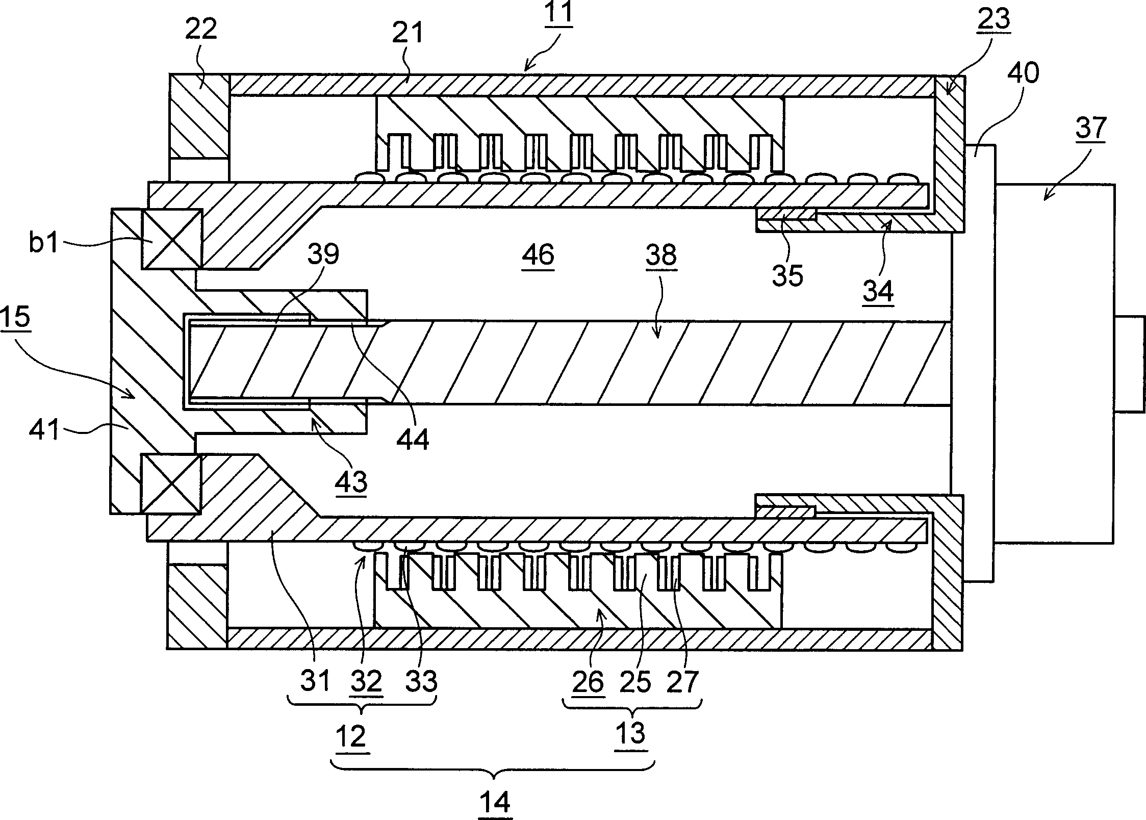
[0043] Fig. 1 is a cross-sectional view of a drive device according to a first embodiment of the present invention. In addition, at this time, the drive unit installed in a molding machine as a mechanical device, such as an injection molding machine, will be described.

[0044]In the figure, 11 is a cylindrical frame, 12 is a cylindrical mover installed freely in the axial direction in the frame 11 (moving in the left and right direction in the figure), and 13 is attached to the frame 11. The cylindrical stator 15 on the inner peripheral surface is a driven body that is rotatable relative to the above-mentioned mover 12 through the bearing b1 and is freely arranged to advance and retreat together with the above-mentioned mover 12. In front of the driven body 15 (Fig. Middle left) is provided with a moving body not shown in the figure so that it can rotate freely and...


PUM


Abstract

The object is to provide an injection molding machine driving device capable of generating a large thrust and of continuous drive with a short cycle. It comprises a casing body (11), a cylindrical linear motor (14) provided with a mover (12) disposed in the casing body (11) for advance and retraction and a stator (13) attached to the casing body (11), the linear motor (14) constituting a first drive section, a driven body (15) advanced and retracted together with the mover (12), and a second drive section attached to the casing body (11) and disposed so as to axially overlap the linear motor (14) at least partially. A slight axial increase in the radial dimension makes it possible to sufficiently increase the area of a permanent magnet (23) for the mover (12), thus increasing the capacity of the linear motor (14).

Description

technical field [0001] The invention relates to a driving device, an injection device and a clamping device of an injection molding machine. Background technique [0002] Conventionally, hydraulic or electric drive devices have been used to generate thrust in various mechanical devices. [0003] In addition, the molding machine in the mechanical device, such as the injection molding machine, injects the resin heated and melted in the heating cylinder with high pressure, fills it into the cavity space of the mold device, and cools and solidifies in the cavity space to become moldings. [0004] The injection molding machine described above has a mold device, a mold clamping device, and an injection device. In addition, the mold device includes a fixed mold and a movable mold, and the mold clamping device includes a fixed platen on which the fixed mold is mounted, a movable platen on which the movable mold is mounted, and a mold clamping mechanism. By making the mold clamping...

Claims


Application Information

Patent Timeline
Patent Type & Authority Applications(China)
IPC IPC(8): B29C45/17B29C45/50B29C45/66
Inventor 金野武司德井洋介
Owner SUMITOMO HEAVY IND LTD
Why Eureka
Try Eureka