Directly controlled pressure control valve

A relief valve, direct technology, applied in the direction of fluid pressure control, non-electric variable control, control/regulation system, etc., can solve the problems of reducing the service life of DBV, unpleasant, high mechanical stress of seat piston, etc., to suppress contact vibration Effect

Inactive Publication Date: 2006-04-05
BOSCH REXROTH AG
View PDF0 Cites 19 Cited by
  • Summary
  • Abstract
  • Description
  • Claims
  • Application Information

AI Technical Summary

Problems solved by technology

[0003] A disadvantage of this solution is that the seat piston performs a rotational or pivotal movement about the sealing ring in the longitudinal direction in the open position
[0004] Due to the joint vibrations generated therein, the seat piston is subjected to high mechanical stress, thereby reducing the service life of the DBV
[0005] Also this contact vibration translates into unpleasant noises such as whistling and prevents low-noise operation

Method used


Image

  • Directly controlled pressure control valve
  • Directly controlled pressure control valve
  • Directly controlled pressure control valve

Examples


Embodiment Construction

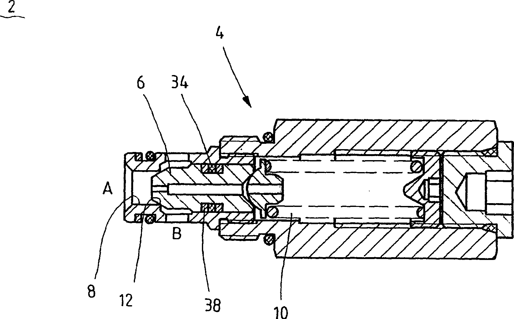
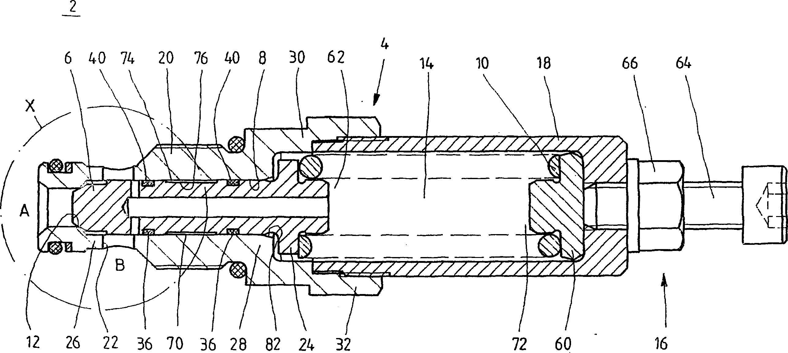
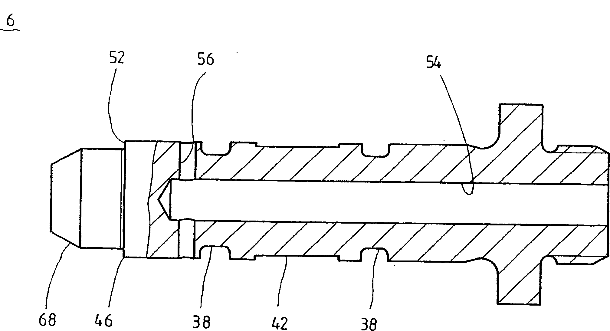
[0023] figure 2 A cutaway side view of a preferred embodiment of a directly controlled overflow valve (DBV) 2 according to the invention is shown. The DBV 2 has a multi-part valve housing 4 comprising a longitudinal bore 8 in which a seat piston 6 is slidably received. Seat piston 6 is biased by spring 10 to its rest position against valve seat 12 . The spring 10 is disposed in a spring cavity 14 and has an adjustable bias via a biasing device 16 .

[0024] The valve sleeve 4 has a spring chamber housing 18 and a seat piston housing 20 . Spring chamber housing 18 bounds spring chamber 14 for receiving spring 10 and is connected to seat piston housing 20 by threaded engagement. In the spring cavity 14 , the spring 10 is supported by the end portion 72 on the bias cover 60 of the bias device 16 . With its second end portion 62 the spring rests on the spring cover 24 of the seat piston 6 .

[0025] The biasing device 16 is arranged in the rear region of the spring chamber h...


PUM


Abstract

The invention relates to a directly controlled pressure control valve comprising a seat piston (6) in a longitudinal borehole (8) of a valve housing (4), said piston being radially guided in the longitudinal borehole, in its guiding region, by means of two peripheral interspaced guiding elements (36).

Description

technical field [0001] The invention relates to a directly controlled overflow valve according to the preamble of claim 1 . Background technique [0002] One such relief valve (DBV) in figure 1 shown in . The DBV shown there was generated from the applicant's record sheet RD 18 016-3.01 / 01.98. figure 1 A DBV 2 is shown comprising a seat piston 6 guided in a valve sleeve 4 . Seat piston 6 is received in longitudinal bore 8 and is biased against valve seat 12 by spring 10 in order to block the hydraulic oil connection from inflow-side working port A to outflow-side working port B. The seat piston 6 is provided with radial play in the longitudinal bore 8 . In a circumferential groove 38 of the seat piston 6 is received a sealing ring 34 which rests sealingly against the inner circumferential wall of the longitudinal bore 8 . [0003] A disadvantage of this solution is that the seat piston performs a rotational or pivotal movement about the sealing ring in the longitudinal ...

Claims


Application Information

Patent Timeline
Patent Type & Authority Applications(China)
IPC IPC(8): F16K17/06G05D16/10F16K17/04
CPCG05D16/10F16K17/065G05D16/103F16K17/0433
Inventor 京特·克伦策彼得·劳尔卡尔-约瑟夫·迈尔
Owner BOSCH REXROTH AG
Why Eureka
Try Eureka