Motorcycle radiator arranging construction
A technology for motorized two-wheeled vehicles and radiators, which is applied in the direction of the combination of cooling of the power unit, the arrangement of the power unit, and vehicle parts, etc., which can solve problems such as being difficult to see, and achieve the promotion of water cooling, improved appearance, and simple installation and structure Effect
- Summary
- Abstract
- Description
- Claims
- Application Information
AI Technical Summary
Problems solved by technology
Method used
Image

Examples
no. 1 Embodiment
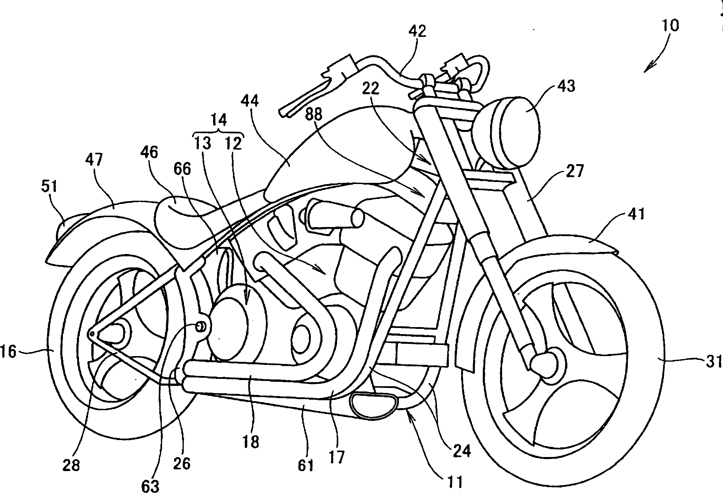
[0071] figure 1 For the perspective view of the motorcycle that adopts the radiator arrangement structure of the present invention, the motorcycle 10 is an American-style vehicle, and a power unit 14 composed of a water-cooled engine 12 and a transmission 13 is mounted on a vehicle frame 11, and the radiator ( (not shown, details will be described later) is arranged between the engine 12 and the rear wheel 16, and the two exhaust pipes (the first exhaust pipe 17 and the second exhaust pipe 18) extending from the engine 12 are shortened.
[0072] This type of vehicle is characterized in that users tend to prefer air-cooled engines, so if the radiator has an inconspicuous appearance, the design will be improved.
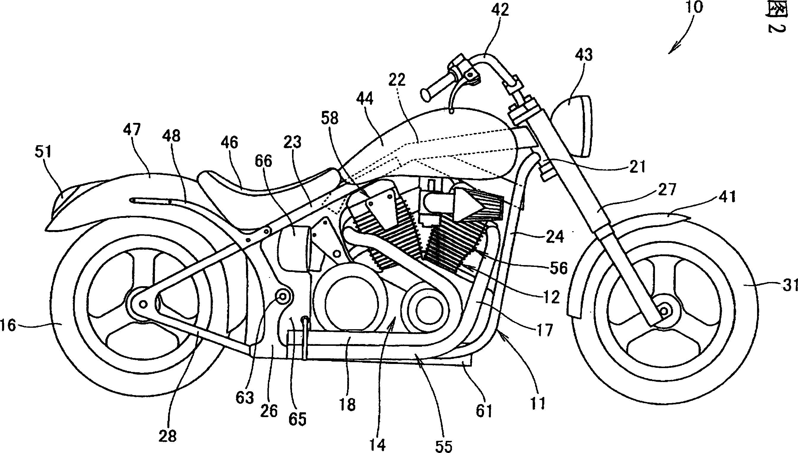
[0073] 2 is a side view of the motorcycle of the present invention. The vehicle frame 11 of the motorcycle 10 includes a head pipe 21, and a pair of left and right main frames 22 extending obliquely downward from the head pipe 21 (only shown) One main frame 22. Herein...
no. 2 Embodiment
[0108] Fig. 8 is a side view of a motorcycle according to a second aspect of the present invention, corresponding to Fig. 2 of the first aspect of the present invention. The same symbols are used for the same members, and the differences from the first embodiment described above will be described below.
[0109] Between the engine 12 and the rear wheel in the figure, in detail, it is the space for disposing the radiator (not shown) between the power unit 14 and the rear wheel 16, and the both sides of the space are covered by the side cover 65. , Intake pipes 66 and exhaust pipes 67 are respectively provided on these side covers 65 .
[0110] 9 is a side view of main parts of a motorcycle according to the second aspect of the present invention, showing the left side of the vehicle frame 11 and power unit 14 as main components. FIG. 9 corresponds to FIG. 3 related to the first aspect of the present invention.
[0111] The radiators 175 and 175 (only the reference numeral 175 ...
no. 4 Embodiment
[0167] Fig. 21 is a side view of a motorcycle according to a fourth embodiment of the present invention, corresponding to Fig. 2 of the first embodiment of the present invention. The same symbols are used for the same members, and the differences from the first embodiment described above will be described below.
[0168] Between the engine 12 and the rear wheel 16 in the figure, in detail, between the power unit 14 and the rear wheel 16 is a space for disposing a radiator (not shown in the figure), and the front of the radiator is covered by the side cover 65. 14 rears are formed on both sides of the space inside the pivot plate 26, and suction pipes 66 are provided on these side covers 65, respectively.
[0169] Figure 22 It is a main part side view of the motorcycle of the present invention (the arrow (front) in the figure represents the front of the vehicle), mainly showing its left side with the vehicle frame 11 and power unit 14, and showing it on the rear fender The s...
PUM
 Abstract
Description
Claims
Application Information
 - R&D
- Intellectual Property
- Life Sciences
- Materials
- Tech Scout
- Unparalleled Data Quality
- Higher Quality Content
- 60% Fewer Hallucinations
Browse by: Latest US Patents, China's latest patents, Technical Efficacy Thesaurus, Application Domain, Technology Topic, Popular Technical Reports.
© 2025 PatSnap. All rights reserved.Legal|Privacy policy|Modern Slavery Act Transparency Statement|Sitemap|About US| Contact US: help@patsnap.com