Superhigh frequency/very high frequency high-gain, broadband directive antenna

A directional antenna, very high frequency technology, applied in the direction of antenna, antenna array, non-resonant long antenna, etc., can solve the problems of low gain, large lateral size of antenna, narrow frequency band, etc., and achieve the effect of wide application value and high gain

Inactive Publication Date: 2006-04-12
XIDIAN UNIV
View PDF0 Cites 6 Cited by
  • Summary
  • Abstract
  • Description
  • Claims
  • Application Information

AI Technical Summary

Problems solved by technology

[0004] The purpose of the present invention is to overcome the deficiencies of the above-mentioned prior art, and provide a UHF / VHF high-gain, wide-band directional antenna to solve the problems of narrow frequency band, low gain and large antenna size in the existing vibrator-type logarithmic periodic antenna. question
[0006] It first designs a single vibrator type logarithmic period antenna according to the conventional method. In order to solve the problem of large lateral size of the antenna, the linear vibrator is changed into a T-shaped structure, and then the same two pairs of T-shaped vibrator type logarithmic period Antennas are arranged in a cone-shaped 2-element array structure, which constitutes the UHF / VHF high-gain, broadband directional antenna of the present invention

Method used


Image

  • Superhigh frequency/very high frequency high-gain, broadband directive antenna
  • Superhigh frequency/very high frequency high-gain, broadband directive antenna
  • Superhigh frequency/very high frequency high-gain, broadband directive antenna

Examples


Embodiment Construction

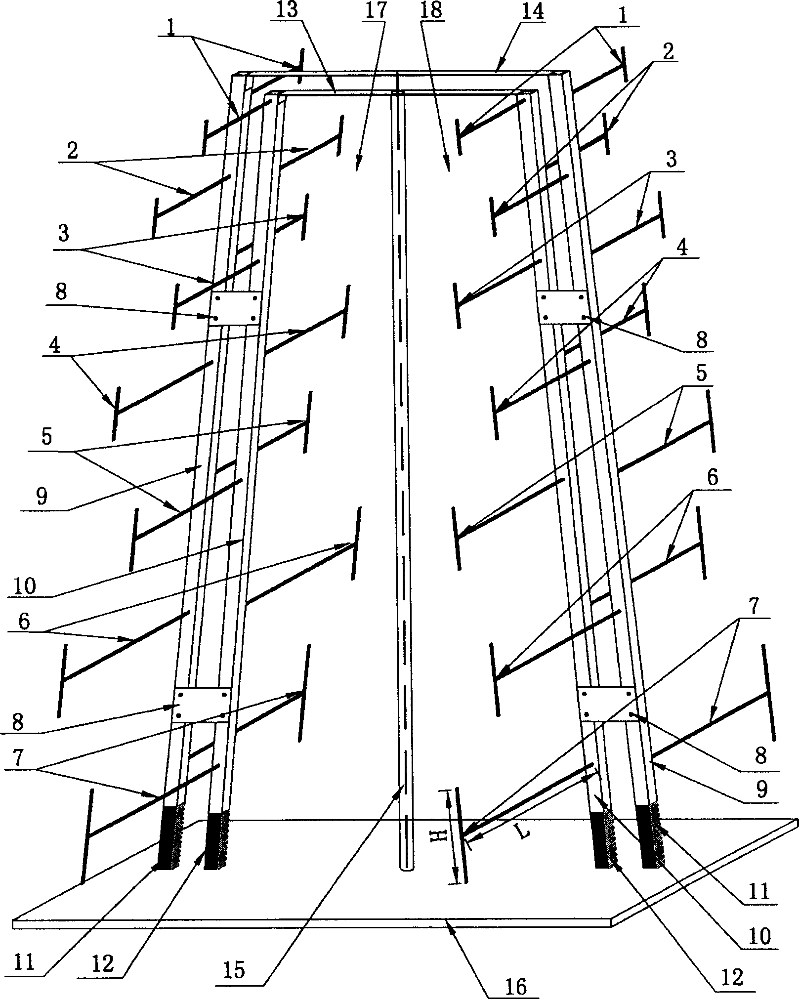
[0027] Reference figure 1 , It is a schematic diagram of the structure of the present invention. The antenna includes a metal ground plate 16, metal connecting strips 13, 14, a hard coaxial cable 15 and two identical T-shaped vibrator-type log periodic antennas 17 and 18. The two identical T-shaped dipole-type log-period antennas 17 and 18 keep the dipoles of the two element antennas parallel, and reduce the distance between the short dipole end of the two element antennas and the long dipole end. The distance between the persons increases, and they are arranged to form a cone-shaped 2-element array structure. The cone-shaped 2-element array structure is installed on the metal ground plate 16, and its upper end is connected with metal connecting bars 13 and 14, and a hard coaxial cable 15 is used to feed signals. The inner conductor of the hard coaxial cable 15 is connected to the metal connecting bar 14. , The outer conductor is connected to the metal connecting strip 13. Two id...


PUM


Abstract

This invention discloses a UHF/VHF high gain and wide band directional antenna applying two same T shaped vibrator log-periodic antennas made of T shaped vibrators arrayed in two-element array structure of a cone and mounted on a metal earth plate connected by two metallic connecting strips at the top and feeding signals with a hard coaxial cable, in which, every antenna is composed of seven T shaped vibrators, a medium fixing plate, two metallic supporting frames and two medium supporting blocks.

Description

Technical field [0001] The invention relates to the technical field of antennas, in particular to a UHF / VHF (UHF / VHF) high-gain, broadband directional antenna, which is used in the fields of communication, navigation, weather detection, nuclear explosion detection and the like. Background technique [0002] As a type of frequency-independent antennas, log periodic antennas were proposed by DHDuHamel and DElsbell in 1957. See DHDuHamel and DElsbell, "BroadbandLogarithmically Periodic Antenna Structures," IRE National ConventionRecord, pt. 1, pp. 119-128, 1957 . The most typical dipole-type log-periodic antenna was published in the scientific paper "Log Periodic Dipole Arrays," authored by DElsbell, IRE Trans Antennas Propagation, Vol.AP-8, pp.260~267, May 1960, about the dipole-type logarithm The analysis and design of periodic antennas can be found in RL Carrel’s Ph.D. Dissertation "Analysis and Design of the Log-Periodic Dipole Antenna," Ph.D. Dissertation, Elec. Eng. Dept., Uni...

Claims


Application Information

Patent Timeline
Patent Type & Authority Applications(China)
IPC IPC(8): H01Q11/10H01Q21/00
Inventor 张福顺焦永昌
Owner XIDIAN UNIV
Why Eureka
Try Eureka