RFID (radiofrequency identification) tag applied to intensive distribution scenarios and mutual impedance design method thereof

A technology of RFID tag and design method, applied in the direction of antenna grounding switch structure connection, radiating element structure form, etc., can solve the problems of reducing system work efficiency, missing tag reading, etc., to improve the transmission coefficient, weak mutual coupling ability, and optimize the antenna. gain effect

Inactive Publication Date: 2014-12-24
SHANGHAI UNIV
View PDF3 Cites 16 Cited by
  • Summary
  • Abstract
  • Description
  • Claims
  • Application Information

AI Technical Summary

Problems solved by technology

For example, in archives and libraries, for a large number of paper materials with thin thickness and dense spacing, when the RFID system is used to achieve long-distance error-free reading, serious label omissions often occur, which reduces the efficiency of the system.

Method used


Image

  • RFID (radiofrequency identification) tag applied to intensive distribution scenarios and mutual impedance design method thereof
  • RFID (radiofrequency identification) tag applied to intensive distribution scenarios and mutual impedance design method thereof
  • RFID (radiofrequency identification) tag applied to intensive distribution scenarios and mutual impedance design method thereof

Examples


Embodiment 1

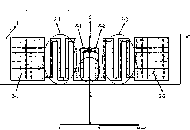
[0040] see Figure 1~Figure 5 , which is applied to an RFID tag used in a densely deployed scene, including a dielectric substrate (1), a metal microstrip antenna and a chip (5) on it, characterized in that: the structure of the metal microstrip antenna is It consists of a pair of radiation patches (2-1, 2-2), a pair of bent radiation arms (3-1, 3-2) and a resonant matching ring (4); the chip (5) is located in the resonant matching At the center point of the upper frame of the ring (4), a bent radiation arm (3-1, 3-2) and a radiation patch (2-1, 2-2) are respectively connected to the left and right sides of the resonant matching ring (4).

Embodiment 2

[0042] This embodiment is basically the same as Embodiment 1, and the special features are as follows:

[0043] The dielectric substrate (1) is a single-sided rectangular structure made of PET polypropylene; the metal microstrip antenna material is copper, which is made by laser engraving on the copper sheet; the pair of radiation patches (2-1 , 2-2) are rectangular, connected to the bent radiation arms (3-1, 3-2), and symmetrically arranged on both sides of the resonant matching ring (4); the pair of bent radiation arms (3- 1, 3-2) are in the shape of a "bow", with 10 bends on each side, connecting the radiation patch (2-1, 2-2) with the resonant matching ring (4), and bending lines of different lengths can be realized Impedance matching and miniaturization of RFID tags; the resonant matching ring (4) is Π-shaped, wherein the transverse arm is connected to the bent radiation arm, the two transverse arms are connected to the feeder (6-1, 6-2), and the feeder It is soldered to...

Embodiment 3

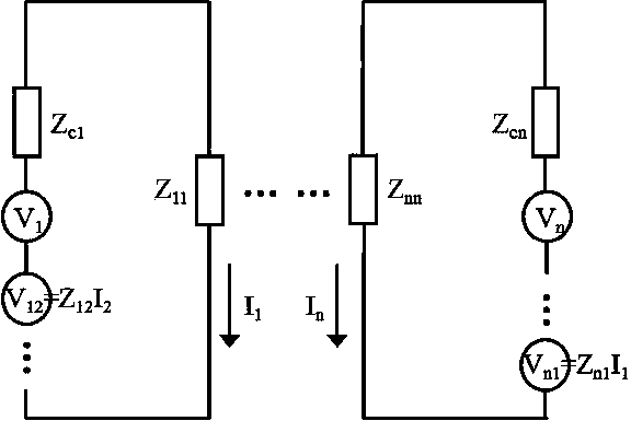
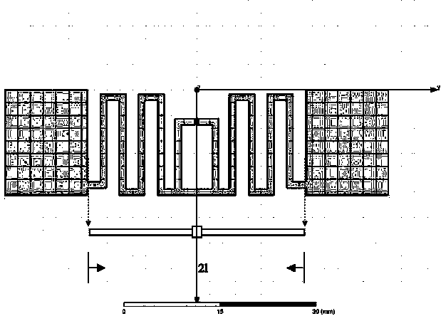
[0045] The mutual resistance design method applied to the RFID tags in the densely deployed scene is applied to the design of the RFID tags applied in the densely deployed scene according to claim 1, and is characterized in that: the RFID tag mutual resistance design method is adopted , according to the calculation formula to find out the influencing parameters of the RFID tag, and use the Ansoft HFSS simulation software to realize the optimal design of the parameters, so that when the RFID tags are densely deployed, the mutual impedance generated is small. The specific operation steps are as follows:

[0046] 1) Calculate the expression of the transmission coefficient of the RFID tag that needs to be identified under the dense deployment of multiple RFID tags at this time, obtain the influencing factors in the formula, and find out the corresponding RFID tag influencing parameters;

[0047] 2) Select the appropriate chip for RFID label production;

[0048] 3) Realize the opti...


PUM


Abstract

The invention relates to an RFID (radiofrequency identification) tag applied to intensive distribution scenarios and a mutual impedance design method thereof. The RFID tag designed comprises a dielectric substrate, a metal microstrip antenna and a chip; the metal microstrip antenna and the chip are arranged on the dielectric substrate. The metal microstrip antenna is composed of a pair of radiation patches, a pair of bent radiation arms and a resonant matching ring. The radiation patches are in a rectangular shape. The bent radiation arms are in an M shape; 10 folds are made on each side of the bent radiation arms. The resonant matching ring is U shaped; two vertical arms of the resonant matching ring are connected with a feeder; the feeder is welded to an anode and a cathode of the chip and connected in a single-port manner. By the use of the mutual impedance design method to the RFID tags, mutual coupling of RFID tags is decreased. The RFID tag has a maximum transmission coefficient 0.8, a maximum gain 2.28dbi and a longest reading distance 10m under operating frequencies; the RFID tag has a wider range of coverage. Under the frequency 920MHz, the RFID tags spaced by 2mm generate mutual impedance less than 50ohm; a good capacity to recognize multiple RFID tags is provided.

Description

technical field [0001] The invention relates to the field of radio frequency identification, in particular to an RFID tag applied in a densely deployed scene and a mutual resistance design method thereof. Background technique [0002] Radio frequency identification technology (RFID) uses radio frequency transmission to establish non-contact two-way communication between readers and tags. The system is mainly composed of the back-end processing unit - the reader and the front-end response unit - the tag. According to the power supply mode, tags can be divided into three types: active, passive, and semi-active; according to the antenna design method, there are dipole antennas, microstrip antennas, slot antennas, etc.; according to the system working mode, there are tags suitable for low frequency, high There are two types of electromagnetic coupling mode tags for high frequency and backscattering mode tags for UHF and microwave bands. [0003] The RFID system communication l...

Claims


Application Information

Patent Timeline
Patent Type & Authority Applications(China)
IPC IPC(8): H01Q1/38H01Q1/50
Inventor 孟春阳彭昌友任秀方李帅田海燕陈文涛
Owner SHANGHAI UNIV
Why Eureka
Try Eureka