
Right-angled piezoelectric cantilever beam vibration energy harvester

A technology of vibration energy collection and cantilever beam, which is applied in the direction of piezoelectric effect/electrostrictive or magnetostrictive motors, generators/motors, electrical components, etc., can solve the problems of single operating frequency, large randomness, and piezoelectric vibration Problems such as energy harvester collection and conversion efficiency reduction, to achieve the effect of small size and simple structure

Inactive Publication Date: 2016-02-03
ZHEJIANG GONGSHANG UNIVERSITY
View PDF5 Cites 16 Cited by
  • Summary
  • Abstract
  • Description
  • Claims
  • Application Information

AI Technical Summary

Problems solved by technology

According to the different principles of energy conversion, there are three types of effective methods for obtaining electric energy: electromagnetic, electrostatic, and piezoelectric. However, traditional piezoelectric energy harvesters generally have problems such as single operating frequency and narrow frequency band. Vibration frequency band is wide and random
When the vibration frequency in the environment slightly deceives the resonance frequency of the piezoelectric vibration energy harvester, the collection and conversion efficiency of the piezoelectric vibration energy harvester will be significantly reduced, which is not conducive to efficient collection and conversion of environmental vibration energy
Therefore, it is still a challenging task to construct a new piezoelectric energy harvester device with a wide operating frequency band.

Method used


Image

  • Right-angled piezoelectric cantilever beam vibration energy harvester
  • Right-angled piezoelectric cantilever beam vibration energy harvester

Examples


Embodiment Construction

[0023] The device of the present invention will be further described in detail below in conjunction with the accompanying drawings.

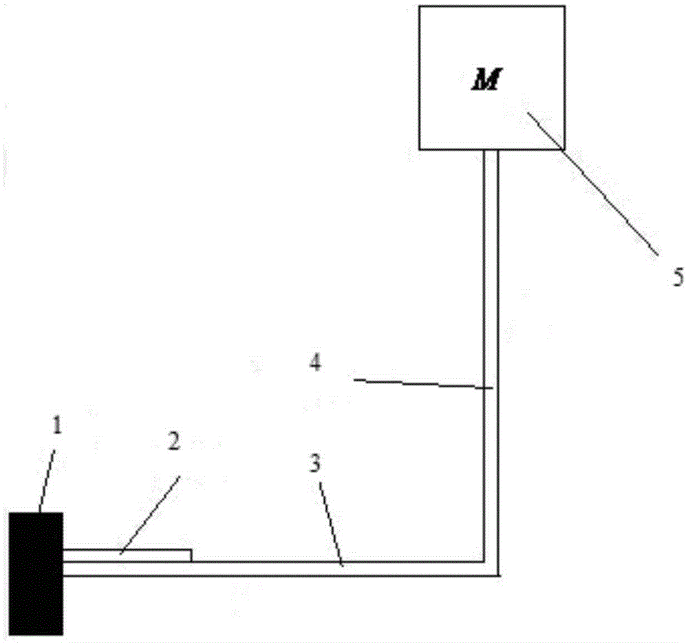
[0024] refer to figure 1 , The right-angle piezoelectric cantilever vibration energy harvester proposed by the present invention consists of a support 1, a piezoelectric ceramic wafer 2, a horizontal metal substrate 3, a vertical metal substrate 4, and a mass 5. The left end of the horizontal metal substrate 3 is fixed on the support 1; the piezoelectric ceramic chip 2 is bonded and fixed on the outer surface of the horizontal metal substrate 3 near the fixed end on the left side through the adhesive layer 6, and the two ends of the vertical metal substrate 4 are connected to the The mass block 5 is connected to the horizontal metal base plate 3; the mass block 5 is fixed at the upper end of the vertical metal base plate 4. The horizontal metal substrate 3 and the vertical metal substrate 4 are perpendicular to each other to form a right-angle ...


PUM

PropertyMeasurementUnit
Lengthaaaaaaaaaa
Lengthaaaaaaaaaa

Abstract

The invention relates to the field of vibration application and electric power technology, and particularly to a right-angled piezoelectric cantilever beam vibration energy harvester. The right-angled piezoelectric cantilever beam vibration energy harvester comprises a supporting base and a horizontal metal substrate which is mounted on the supporting base. The horizontal metal substrate is provided with a piezoelectric ceramic wafer at the end which is next to the supporting base. A vertical metal substrate is adhered to the other end of the horizontal metal substrate. The horizontal metal substrate is perpendicular with a vertical metal substrate, thereby forming a right-angled cantilever beam structure. The other end of the vertical metal substrate is provided with a mass block. According to the right-angled piezoelectric cantilever beam vibration energy harvester, the right-angled cantilever beam is formed through adding an auxiliary cantilever beam at the end of the horizontal cantilever beam. Through controlling the structural dimensions of the horizontal cantilever beam and the vertical cantilever beam and the mass of the mass block, controlling for an interval between two front stages of modal frequencies is realized, thereby forming a relatively wide operation frequency band and realizing high-efficiency acquisition and conversion for environment vibration energy.

Description

technical field [0001] The invention relates to the fields of vibration application and electric power technology, in particular to a vibration energy harvester of a right-angle piezoelectric cantilever beam. Background technique [0002] Now chemical batteries are the main power supply for micro-sensors, integrated circuits, MEMS and portable electronic devices, but the battery life is limited and needs to be replaced regularly, which will inevitably bring inconvenience to system applications, especially for the increasingly rapid development of medical health monitoring and embedded For mobile smart systems, this limitation of battery power supply is even more obvious. In addition, a large number of batteries will bring problems such as waste of materials and environmental pollution. Therefore, finding a sustainable power supply method to replace battery power supply is a key technology to break through the bottleneck of system life. [0003] Vibration is one of the most...

Claims


Application Information

Patent Timeline
IPC IPC(8): H02N2/18
CPCH02N2/188
Inventor 张伟王光庆
Owner ZHEJIANG GONGSHANG UNIVERSITY
Learn More