Digital control electric chuck for lathe

An electric chuck, lathe technology, applied in the direction of chucks, turning equipment, tool holder accessories, etc., can solve the problems of inconvenient use, troublesome adjustment of the center of the four-jaw chuck, and the chuck cannot be used universally, and achieves accurate action, Adjustable effects

Inactive Publication Date: 2006-04-19
王洋
View PDF0 Cites 10 Cited by
  • Summary
  • Abstract
  • Description
  • Claims
  • Application Information

AI Technical Summary

Problems solved by technology

[0003] Since the three-jaw chuck cannot be used to clamp square workpieces, it is troublesome to adjust the center of the circle when using the four-jaw chuck, and the two types of chucks cannot be used in common, causing inconvenience in use

Method used


Image

  • Digital control electric chuck for lathe
  • Digital control electric chuck for lathe
  • Digital control electric chuck for lathe

Examples


Embodiment Construction

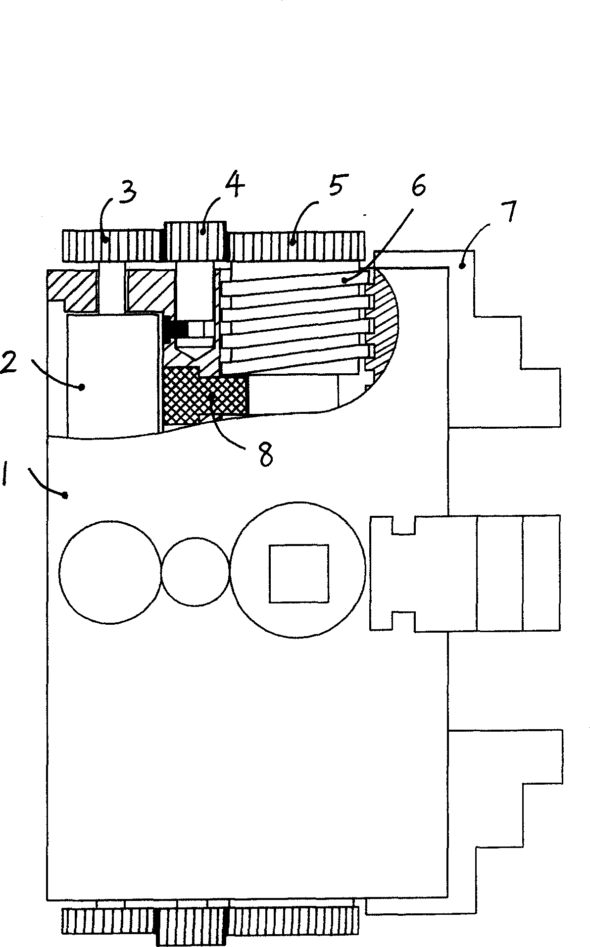
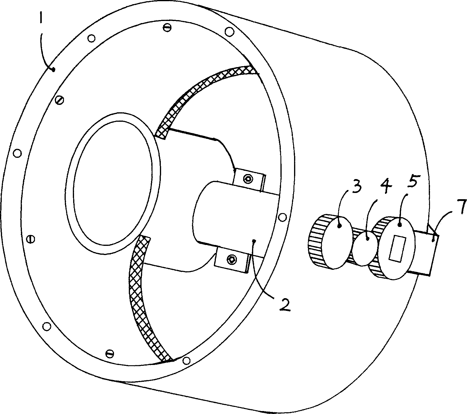
[0014] combine figure 1 with figure 2 , the lathe numerical control electric chuck of embodiment, comprise chuck body 1, the claw 7 that is installed one by one by four claw chute of chuck body, the back of claw 7 is shaped on screw tooth, the claw on the chuck body Four screw rods 6 are respectively arranged at the corresponding positions of the rear part, and the screw rods 6 are engaged with the claws 7 one by one, and these structures are the same as those of the existing four-jaw chuck.

[0015] The screw rod 6 is provided with a driven gear 5, and in the chuck body, four motors 2 are respectively arranged at the corresponding positions of the rear part of the screw rod 6, and the driving gear 3 is fixed on the motor shaft, between the driving gear 3 and the driven gear 5. An intermediate gear 4 is also provided, and the driving gear 3 and the driven gear 5 are engaged and connected through the intermediate gear 4 .

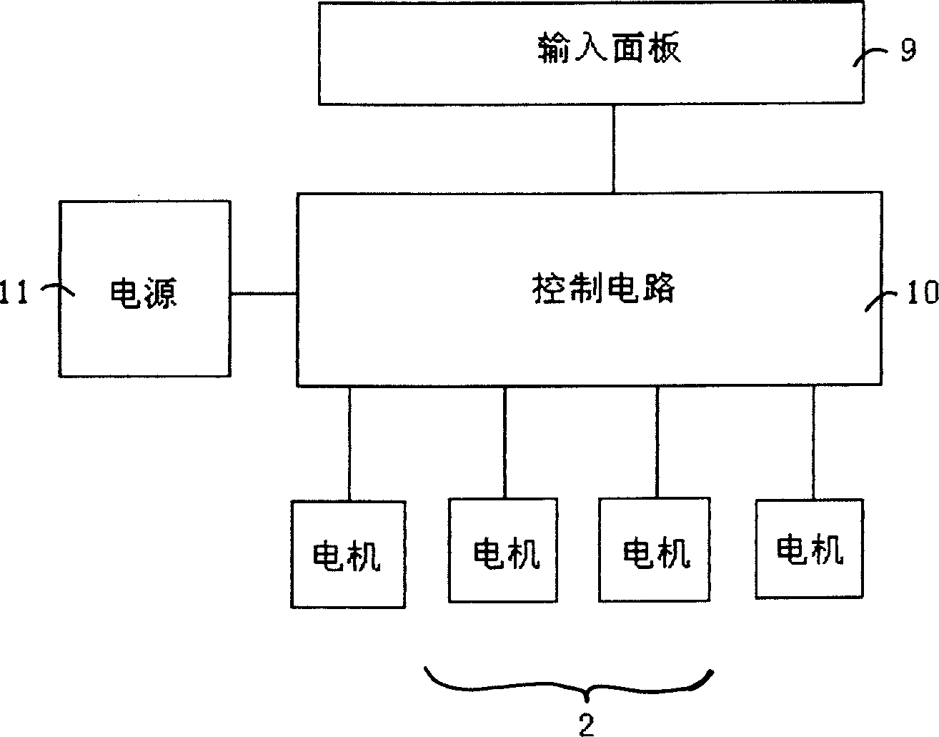
[0016] During installation, the control device comp...


PUM


Abstract

A numerally controlled electric chuck of lathe is based on existing 4-jaw chuck. Its screw bolt has the driven gear for driving the jaw. The 4 drive gears engaged with said driven gear via intermediate gears are installed to 4 rotary shafts of 4 motors respectively. Its controller unit with controller and control panel is installed on lathe. Said 4 motors are respectively connected to relative outputs of control circuit.

Description

technical field [0001] The present invention relates to machine tool components, particularly improvements to lathe chucks. Background technique [0002] On lathes, there are two kinds of chucks used to clamp workpieces: three-jaw and four-jaw. The three-jaw chuck is equipped with three claws on the chuck body, and each claw meshes with a toothed disc with a spiral tooth groove through the teeth on the back. The three small bevel teeth mesh with each other. Turn any one of the small bevel teeth during use to drive the tooth plate to rotate, so that the three jaws advance and retreat synchronously to clamp round workpieces; the four-jaw chuck consists of a chuck body, four chucks Claws and four screw rods, the chuck body is equipped with four claws, the screw rod is set in the chuck body along the radial direction, corresponding to the position of the claws, and each claw is meshed with each screw through the teeth on the back. , turn the screw, the jaws move in the jaw chu...

Claims


Application Information

Patent Timeline
Patent Type & Authority Applications(China)
IPC IPC(8): B23B31/28B23B31/165
Inventor 李杰占炜王滢
Owner 王洋
Why Eureka
Try Eureka