Condensed-water discharging system and control method thereof

A technology of drainage system and condensate water, applied in the direction of evaporator accessories, etc., can solve the problems of low degree of automation, affecting the dynamic balance of impellers, and high operating power of pumps, and achieves the effect of reducing labor workload, improving labor efficiency and high degree of automation

Active Publication Date: 2014-04-02
江苏纵横浓缩干燥设备有限公司
View PDF2 Cites 5 Cited by
  • Summary
  • Abstract
  • Description
  • Claims
  • Application Information

AI Technical Summary

Problems solved by technology

When the secondary evaporation is sucked into the fan along the pipeline, part of it is condensed into condensed water, and the secondary steam entering the fan volute will also produce a part of condensed water during the compression and heating process, and the compressed and heated steam re-enters the evaporator through the pipeline There will be very little steam condensation to produce condensed water flowing into the fan along the pipe wall. If these three parts of condensed water are not dealt with in time, it will affect the dynamic balance of the impeller and the stability of the entire fan operation.
At present, the method of directly discharging these two parts of condensed water with a pump is generally adopted in China, which has a low degree of automation, and the operating power of the pump is high, and the cost is relatively high.

Method used


Image

  • Condensed-water discharging system and control method thereof

Examples


Embodiment 1

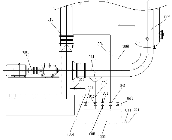
[0008] Embodiment 1: A condensed water drainage system, the drainage system is used for the MVR evaporator, the MVR evaporator includes a mechanical compression fan 001 and a vacuum system 002, it is characterized in that it includes a condensate storage tank 003, and the condensate storage The top of the tank 003 is provided with three condensed water inlet pipes 004 respectively connected to the water collecting bucket 011 before the inlet of the mechanical compression fan 001, the condensed water outlet 012 at the inner bottom of the volute of the mechanical compression fan and the outlet 013 of the mechanical compression fan. The top of the tank 003 is provided with a row of vacuum pipes 005 and a vacuum pipe 006 connected to the vacuum system 002, the bottom of the condensate storage tank 003 is provided with a condensate discharge pipe 007, and the three condensate water inlet pipes 004 are all provided with There is a normally open solenoid valve 041, the vacuum exhaust ...


PUM


Abstract

The invention discloses a condensed-water discharging system and a control method thereof. The condensed-water discharging system is used for an MVR evaporator which comprises a mechanical compression fan and a vacuumizing system. The condensed-water discharging system comprises a condensing storage tank, wherein the top part of the condensing storage tank is provided with three condensed-water pipelines which are respectively connected with a water collecting hopper at the front of an inlet of the mechanical compression fan, a condensed-water discharging port at the bottom end in a volute of the mechanical compression fan and an outlet of the mechanical compression fan; the top part of the condensed-water storage tank is also provided with a vacuum exhausting pipeline and a vacuum pumping pipeline which is connected with a vacuum pumping system; the bottom end of the condensed-water storage tank is provided with a condensed-water discharging pipeline; the three condensed-water feeding pipelines are respectively provided with a normally-opened electromagnetic valve; the vacuum exhausting pipeline is provided with a normally-opened electromagnetic valve; the vacuum pumping pipeline is provided with a normally-closed electromagnetic valve; the condensed-water discharging pipeline is provided with a normally-closed electromagnetic valve. The condensed-water discharging system and the control method disclosed by the invention have advantages that the automation degree is high, the labor amount of workers is reduced, the labor efficiency is improved and the operation power is greatly reduced.

Description

technical field [0001] The invention belongs to the field of new energy, high efficiency and energy saving-industrial energy saving, and specifically relates to a condensed water drainage system for an MVR evaporator used for solution concentration. Background technique [0002] MVR evaporator is a high-efficiency and energy-saving evaporation concentration equipment, which uses electric energy instead of steam as the evaporation heat source. Compared with the traditional evaporator, it introduces more mechanical compressor fan parts, but the operating cost is much lower than the multi-effect evaporator unit that directly uses steam as a heat source. The MVR evaporator only needs to use a small amount of raw steam as the heat source of the heater when it is running. The solution in the evaporator is heated and vaporized to generate secondary steam, which is sucked into the mechanical compression fan and added to the saturated secondary steam through the mechanical energy of ...

Claims


Application Information

Patent Timeline
Patent Type & Authority Applications(China)
IPC IPC(8): B01D1/30
Inventor 王盛刘泽勇姚永忠
Owner 江苏纵横浓缩干燥设备有限公司
Why Eureka
Try Eureka